
Code_Aster
®
Version
6.4
Titrate:
Postprocessing according to RCC-M'S
Date:
03/03/03
Author (S):
J.M. PROIX
Key
:
R7.04.03-B
Page
:
1/32
Manual of Reference
R7.04 booklet: Evaluation of the damage
HT-66/02/004/A
Organization (S):
EDF/AMA
Manual of Reference
R7.04 booklet: Evaluation of the damage
Document: R7.04.03
Postprocessing according to RCC-M'S
Summary:
Operator POST_RCCM allows to check the criteria of level 0 and certain criteria of level A of
RCC-M-B3200, for modelings of continuous mediums 2D or 3D.
It also allows the calculation of the criteria of fatigue of the §B3600 in postprocessing of calculations of pipings.
The criteria defined in the B3200 chapter of the RCC-M utilize significant sizes that one
compare with limiting values.
The criteria of level 0 aim at securing the hardware against the damage of excessive deformation,
of plastic instability and elastic and elastoplastic instability. These criteria require the calculation of
equivalent stresses of Pm membrane, local membrane Pl and membrane plus Pm+Pb bending.
order
POST_RCCM
calculate Pm or Pl and Pm+Pb.
The criteria of level A aim at securing the hardware against the damage of progressive deformation and of
tire. Except fatigue, they require the calculation of the amplitude of variation of linearized, noted stress Sn, and
possibly of the quantity Sn *. For fatigue, they require in more calculation of the amplitude of variation of
stress in a point, noted Sp.
The control
POST_RCCM
[U4.67.04] carries out calculations of Sn, Sn *, Sp and of the number of acceptable cycles
in fatigue. In postprocessing of analyzes of pipings, option FATIGUE_B3600 allows calculation factor
of use in fatigue by taking into account all the calculated situations.
Code_Aster
®
Version
6.4
Titrate:
Postprocessing according to RCC-M'S
Date:
03/03/03
Author (S):
J.M. PROIX
Key
:
R7.04.03-B
Page
:
2/32
Manual of Reference
R7.04 booklet: Evaluation of the damage
HT-66/02/004/A
Count
matters
5.2.2
Calculation of the combinations of loading (I, J) for the situations of passage between group

Code_Aster
®
Version
6.4
Titrate:
Postprocessing according to RCC-M'S
Date:
03/03/03
Author (S):
J.M. PROIX
Key
:
R7.04.03-B
Page
:
3/32
Manual of Reference
R7.04 booklet: Evaluation of the damage
HT-66/02/004/A
6.1.5
Calculation of the amplitudes of stresses for the situations of passage between group of

Code_Aster
®
Version
6.4
Titrate:
Postprocessing according to RCC-M'S
Date:
03/03/03
Author (S):
J.M. PROIX
Key
:
R7.04.03-B
Page
:
4/32
Manual of Reference
R7.04 booklet: Evaluation of the damage
HT-66/02/004/A
1
Criteria of the RCC-M B3200. Adaptation to Code_Aster
The B3200 chapter of the RCC-M [bib1] described the general rules of analysis of the behavior of
hardware of level 1 of the Nuclear thermal power stations. These rules make it possible to ensure the safeties
necessary with respect to the damage to which this hardware is subjected. For that one defines
various levels of criteria in each category of situation which make it possible to compare
significant sizes with limiting values. The adaptations necessary to Code_Aster are
described here, and justified in [bib2].
1.1 Data
geometrical
The user of the RCC-M must distinguish in his structure the areas of major discontinuity, the areas
of minor discontinuity and areas comprising of the geometrical singularities. The RCC-M defines
“segments of support” which are used to linearize the stresses. These segments are, out of the areas of
discontinuity, of the generally normal segments on the median surface of the wall, and in
areas of discontinuity, shortest segments allowing to join the 2 faces of the wall.
The user of ASTER must thus define the whole of the sections of the structure where calculations of post-
processing will be made (it is him which knows if these sections pass by current areas, or areas
of geometrical discontinuity). In practice, one works on a segment provided by
INTE_MAIL_2D
or
INTE_MAIL_3D
. One systematically calculates all the criteria at the two ends of the segment, or
more precisely with the two intersections of the segment with the edges of the structure.
1.2
Data of loading
The user of the RCC-M must give the number of occurrences of each situation of operation
(for example: heating of the boiler, hot stop, etc.). A situation of operation can
to be broken up into transients, i.e. of the evolutions of the parameters of operation
total (pressure, temperature) according to time.
In ASTER, one treats mechanical results (produced by
MECA_STATIQUE
or
STAT_NON_LINE
), therefore transients. For each transient, the stress fields are
provided to the moments of discretization of calculation.
1.3 Data
material
The data material required are as follows:
·
Sm: acceptable value (tabulée in the RCC-M Annexes Z1).
·
m, N: constant material for the calculation of Ke (defined in the RCC-M B3234.6)
·
EC., E: moduli of elasticity (for the correction of the curve of fatigue, annexes Z1).
·
Curves of fatigue of material: according to RCC-M'S annexes Z1.
1.4 Assumptions
simplifying
In the RCC-M, the user must be able to say, after analysis of the results of calculation, if them
main directions in a given point are fixed or if they turn in the course of time.
On the other hand, in control POST_RCCM, one can not make an assumption. One will not consider
that the case where the main directions are unspecified.

Code_Aster
®
Version
6.4
Titrate:
Postprocessing according to RCC-M'S
Date:
03/03/03
Author (S):
J.M. PROIX
Key
:
R7.04.03-B
Page
:
5/32
Manual of Reference
R7.04 booklet: Evaluation of the damage
HT-66/02/004/A
Moreover, the user must be able to classify the stresses in the following categories:
·
General primary education of membrane: Pm
·
Primary education of local membrane: Pl
·
Primary education of bending: Pb
·
Thermal expansion: EP
·
Secondary: Q
·
Of point: F
This choice cannot be made by
POST_RCCM
. Only the user can qualify a stress field
(“Primary education”, “secondary”, or summon it of both). The criteria which are to be checked are calculated to leave
stress fields (constant or function of time) provided by the user. It is him which ensures
coherence enters the calculation of these fields and the criteria applied.
However, to fix the ideas, classification is simpler in the following cases:
·
a constant or variable loading with imposed force or pressure is primary, except for
certain very particular structures,
·
a constant or variable loading with imposed displacement is in theory, secondary (except
in the case of “the effect spring”),
·
a permanent or transitory thermal loading is in theory secondary.
On the other hand, the combination of these types of loadings leads to a result which cannot be any more
qualified of primary education or secondary. According to the criteria, the user could thus be brought to
to break up its loadings.
1.5
Calculations carried out by
POST_RCCM
The operation of the control here is described
POST_RCCM
allowing to carry out the calculation of
certain criteria RCC-M B3200 of levels 0 and A. the realization described here does not take into account
touts the criteria of B3200 and could be supplemented (for example for other levels of criteria,
or for criteria of the RCC-MR,…).
The main data is the segment (of support) where calculations will be carried out. It is the user who
the segment chooses and which with the responsibility to find that for which quantities intervening in
the criteria are maximum. The automatic search for this segment carrying out the maximum is one
difficult problem, and is not programmed.
After having calculated one or more results by
MECA_STATIQUE
or
STAT_NON_LINE
, and definite it
segment by
INTE_MAIL_2D
or
_3D
, the user asks for the calculation of the criteria by the operator
POST_RCCM
.
Three types of criteria are accessible each one by a key word factor:
·
criteria of level 0 by the key word
PM_PB
,
·
criteria of level A (except fatigue) by the key word
SN
,
·
criteria of fatigue (also of level A) by the key word
TIRE
.

Code_Aster
®
Version
6.4
Titrate:
Postprocessing according to RCC-M'S
Date:
03/03/03
Author (S):
J.M. PROIX
Key
:
R7.04.03-B
Page
:
6/32
Manual of Reference
R7.04 booklet: Evaluation of the damage
HT-66/02/004/A
2
Criteria of level 0 (key word
PM_PB
)
2.1
Criteria of level 0 specified by the RCC-M
The criteria of level 0 aim at securing the hardware against the damage of excessive deformation,
of plastic instability and elastic and elastoplastic instability. They must be checked by the situation
of reference (see B3121 and B3151). These criteria require the calculation of the stresses
equivalent
P
P P
m
I
B
,
,
who are below defined.
2.1.1 General primary equivalent stress of Pm membrane
Being given the primary stress of the situation of reference (1
E
category) and a segment located out
of an area of major discontinuity. In each point end of this segment length
L
, one
calculate:
()
()
(
)
P
L
ds
m
T
ijmoy Eq Tresca
ijmoy
ij
L
ij Eq Tresca
I J
I
J
I I
=
=
=
-
=
max
,
max
.
.
,
,
where
are the main stresses
1
0
1 3
The criterion is written:
P
S
m
m
2.1.2 Primary equivalent stress of local membrane Pl
Being given the primary stress of the situation of reference (1
E
category) and a segment located
in an area of major discontinuity, the definition of
P
I
is identical to that of
P
m
on it
segment.
The criterion is written:
P
S
I
m
15
.
2.1.3 Primary equivalent stress of membrane+flection Pmb (or Plb)
Being given the primary stress of the situation of reference (1
E
category) and a segment (directed).
In each point end of this segment length
L
, (ends corresponding to the skins
external and intern), one calculates:
()
()
()
(
)
(
)
P
P
P
L
ds
L
S
L
ds
S
S
m
T
ijmoy Eq Tresca
B
T
ijfle Eq Tresca
mb
T
ijlin Eq Tresca
ijmoy
ij
L
ijfle
ij
L
ijlin
ijmoy
ijfle
ijlin
ijmoy
ijfle
ijlin
ijmoy
ijfle
=
=
=
=
=
-
=
±
=
=
-
= =
+
max
max
max
.
.
.
1
6
2
0
0
2 0
L

Code_Aster
®
Version
6.4
Titrate:
Postprocessing according to RCC-M'S
Date:
03/03/03
Author (S):
J.M. PROIX
Key
:
R7.04.03-B
Page
:
7/32
Manual of Reference
R7.04 booklet: Evaluation of the damage
HT-66/02/004/A
The criteria are written:
P
S
P
S
mb
m
Ib
m
15
15
.
.
2.2
Calculations carried out by Aster
It is with the user to know if one calculates Pm (forced general of membrane: out of the areas of
geometrical singularity) or Pl (forced local of membrane: in the singularities). To leave
stress fields provided (in the result), a membrane stress is thus calculated.
The concept result comprises either only one stress field, or of the fields resulting from one
evolution. In this last case, one will seek the maximum compared to the list of the sequence numbers
terms intervening in the criteria.
The algorithm is as follows:
Impression of the segment (cf
POST_RELEVE
)
·
On the whole of the nbmax, sequence numbers n=1
-
extraction of the moment T
-
on each end of the segment
-
calculation of Pm and Pmb by integrations on the segment
()
P
L
ds
m
T
ijmoy Eq Tresca
ijmoy
ij
L
=
=
max
,
.
1
0
()
(
)
(
)
P
L
S
L
ds
P
S
P
S L
B
T
ijfle Eq Tresca
ijfle
ij
L
mb
T
ijmoy
ijfle Eq Tresca
mb
T
ijmoy
ijfle Eq Tresca
=
=
-
=
=
-
= =
+
max
,
(
)
max
(
)
max
.
.
.
6
2
0
2 0
-
Seek maximum of P
m
, P
mb
(s=0), P
mb
(s=l).
-
Exit and storage in the table of the result.
The values limit are Sm and 1.5 Sm, Sm being working stress function of material and of
temperature, given by mot_clé
SM_KE_RCCM
behavior
TIRE
in
DEFI_MATERIAU
.

Code_Aster
®
Version
6.4
Titrate:
Postprocessing according to RCC-M'S
Date:
03/03/03
Author (S):
J.M. PROIX
Key
:
R7.04.03-B
Page
:
8/32
Manual of Reference
R7.04 booklet: Evaluation of the damage
HT-66/02/004/A
3
Criteria of level A (except fatigue) (key word
SN)
3.1
Criteria of level A specified by the RCC-M
This option makes it possible to calculate the criteria of level A (except fatigue) which aim at securing the hardware
against the damage of progressive deformation. They require the calculation of the amplitude of variation
linearized more secondary primary stresses, noted S
N
.
3.1.1 Sn calculation
One takes into account the more secondary primary stresses and the stresses resulting from
opposed thermal dilations: P
L
+ P
B
+ P
E
+ Q which thus represents the linearized stresses
associated all the loading (mechanical and thermal).
The points of calculation are the two ends of the segment (given by the key word
PATH
). In each
not end of this segment length
L
, one calculates:
()
()
(
)
(
)
(
)
S
T
T
L
ds
L
S
L
ds
S
S
N
T
T
ijlin
ijlin
Eq Tresca
ijmoy
ij
L
ijfle
ij
L
ijlin
ijmoy
ijfle
ijlin
ijmoy
ijfle
ijlin
ijmoy
ijfle
=
-
=
=
-
=
±
=
=
-
= =
+
max max
.
1
2
1
2
0
2 0
1
6
2
0
L
The criterion (of total adaptation) is written:
S
S
N
m
3
S
m
being the working stress function of material and temperature, given by mot_clé
SM_KE_RCCM
behavior
TIRE
in
DEFI_MATERIAU
.
If this criterion is not checked, one can practice the simplified elastoplastic analysis of B3234.3. It is necessary
to carry out the three following operations:
·
to check the criterion:
S
S
N
m
*
3
·
to make an elastoplastic correction (Ke > 1) in the analysis with fatigue,
·
to check the rule of Bree (B3234.8) in the current parts of the cylindrical hulls (and
pipes) subjected to a pressure and a variation in cyclic temperature. This relates to one
very particular situation and will thus not be described here.
3.1.2 Sn calculation *
One notes
S
N *
the amplitude Sn calculated without taking into account bending stresses of origin
thermics. One calculates for each end:
()
()
(
)
()
()
(
)
(
)
S
T
T
T
T
L
S
L
ds
N
T
T
ijlin
ijfleth
ijlin
ijfleth
Eq Tresca
ijfleth
ijth
L
*
*
.
max max
=
-
-
-
=
-
1
2
1
1
2
2
2 0
6
2

Code_Aster
®
Version
6.4
Titrate:
Postprocessing according to RCC-M'S
Date:
03/03/03
Author (S):
J.M. PROIX
Key
:
R7.04.03-B
Page
:
9/32
Manual of Reference
R7.04 booklet: Evaluation of the damage
HT-66/02/004/A
ij
HT
coming from a calculation carried out with the thermal loading only (i.e. which one removes from
complete calculation, having led to the Sn value, all the loadings other than the loading
thermics).
3.2
Calculations carried out by Aster
3.2.1 Sn calculation
From the moments of calculation selected in the result, one thus calculates S
N
at each end of
segment. If it y does not have calculation at the moment T = 0, one creates a stress field identically no one with
T = 0.
The algorithm is as follows:
Impression of the characteristics of the segment (cf
POST_RELEVE
)
·
on the whole of the N, sequence numbers
1
=1, nbmax
-
Extraction of the moment T
1
-
calculation of
ijlin
T S
(,
)
1
0
=
and
ijlin
T S L
(,
)
1
=
-
For N
2
varying N
1
+1 with nbmax
-
Extraction of the moment T
2
-
calculation of
ijlin
T S
(,
)
2
0
=
and
ijlin
T S L
(,
)
2
=
and of
ijlin
ijlin
T S
T S
(,
)
(,
)
2
1
0
0
= -
=
and
ijlin
ijlin
T S L
T S L
(,
)
(,
)
2
1
= -
=
-
calculation of the main directions and the criterion of Tresca:
(
)
(
)
(
)
ijlin
ijlin
Eq Tresca
T S
T S
2
1
0
0
,
,
.
= -
=
and
(
)
(
)
(
)
ijlin
ijlin
Eq Tresca
T S L
T S L
2
1
,
,
.
= -
=
-
thus seek maximum of S
N
Exit and storage in the table of the result.
3.2.2 Calculation of S
N
*
This calculation is carried out if the operand
RESU_SIGM_THER
is present. Only the user ensures
coherence, i.e. this result must be produced by a thermomechanical calculation under
thermal loading only, knowing that the result given by
RESULT
can be due to one
combination of this thermal loading with other loadings. It is necessary thus that the moments of
this result correspond to those of the result associated with the key word
RESULT
.
The algorithm is identical to the precedent but relates to two stress fields.

Code_Aster
®
Version
6.4
Titrate:
Postprocessing according to RCC-M'S
Date:
03/03/03
Author (S):
J.M. PROIX
Key
:
R7.04.03-B
Page
:
10/32
Manual of Reference
R7.04 booklet: Evaluation of the damage
HT-66/02/004/A
4
Criteria of fatigue (of level A) (key word
TIRE
)
In the case of fatigue it should be made sure that the factor of total use - which integrates the effect of
combinations of situations 2 to 2 - is lower than 1. For this analysis one needs:
·
on the one hand, of S
N
previously defined, which requires the linearization of the stresses, this
to calculate the elastoplastic concentration factor K
E
,
·
in addition, of S
p
who is the amplitude of variation of total stresses (P
L
+ P
B
+ P
E
+ Q + F),
who does not require linearization, and who whose definition follows. This S
p
is used to calculate
equivalent stress alternate S
alt
who, via the curves of fatigue, allows to determine it
factor of use.
We present two methods:
·
the first makes it possible to calculate the factor of use for only one transient (according to the RCC-M
B3234.5). It is supposed here that the transient does not comprise secondary fluctuations
(each quantity varies between an always identical minimum and a maximum),
·
the second method makes it possible to combine several transients and to take account of
factors of use specific to the secondary fluctuations (additional RCC-M ZH210).
It is also supposed that one is not located in areas comprising of the singularities
geometrical (if not, it is necessary to apply the methods of calculation to the priming of the singular areas which
are the subject of appendix ZD of the RCC-M).
4.1
First method: maximum amplitude in a transient
It is a first approach of the calculation of the damage of fatigue of the RCC-M B3200, limited to
processing of only one transient (not of combination of transients) and without consideration of
under-cycles. This method is the only available one in version 3 of Code_Aster (it is activated by
key word `
FATIGUE_SPMAX
'in version 4). One calculates the amplitude of variation of stress in one
, not noted S
p
, and the amplitude of variation of linearized stress Sn for the calculation of the factor of
elastoplastic correction K
E
(according to the RCC-M B3200).
In each point end of the segment length
L
, one calculates:
()
()
(
)
()
()
(
)
S
T
T
S
T
T
L
ds
L
S
L
ds
p
T
T
ij
ij
Eq Tresca
N
T
T
ijlin
ijlin
Eq Tresca
ijmoy
ij
L
ijfle
ij
L
ijlin
ijmoy
ijfle
=
-
=
-
=
=
-
=
±
max max
max max
.
.
1
2
1
2
1
2
1
2
0
2 0
1
6
2
then
()
S
E
E K S S
alt
C
E
N
p
=
1
2
and by the curve of fatigue of Wöhler:
()
NR
F S
adm
alt
=
.
An acceptable value of K
E
can be given according to the RCC-M B3200 as follows:
()
()
()
K S
S
S
K S
N
N m
S
S
S
S
m S
K S
N
S
m S
E
N
N
m
E
N
N
m
m
N
m
E
N
N
m
=
<
= +
-
-
-
<
<
=
>
1
3
1
1
1 3
1
3
3
1
3
if
if
if
(
)

Code_Aster
®
Version
6.4
Titrate:
Postprocessing according to RCC-M'S
Date:
03/03/03
Author (S):
J.M. PROIX
Key
:
R7.04.03-B
Page
:
11/32
Manual of Reference
R7.04 booklet: Evaluation of the damage
HT-66/02/004/A
The values of m and N are given in B3234.6 of the RCC-M. These parameters and the curve of
fatigue are introduced into the control
DEFI_MATERIAU
[U4.23.01] under the key word factor
TIRE
.
·
N
corresponds to
N_KE_RCCM
·
m
corresponds to
M_KE_RCCM
·
S
m
corresponds to
SM_KE_RCCM
·
The Young modulus of reference of the curve of fatigue EC. corresponds to
E_REFE
.
Young modulus corresponding to calculation carried out is defined classically under the key word
factor
ELAS
.
·
The curve of fatigue
()
NR
F S
adm
alt
=
is a function defined by
DEFI_FONCTION
, and
introduced into
DEFI_MATERIAU
by the key word
WOHLER
key word factor
TIRE.
This algorithm is directly deduced from the calculation of S
N
and S
p
maximum for only one transient and
does not take into account the under-cycles. It thus does not correspond to that of
POST_FATIGUE
.
If the user wishes at the same time the S and fatigue analysis
N
for the transient, it can occur to use
the key word S
N
, because the calculation of S
alt
imply two calculations:
·
that of S
p
·
that of S
N
carried out previously.
As for the criterion S
N
< 3S
m
, as from every moment of calculation, one calculates S
p
with each
end of the segment. If only one moment ago, one creates a fictitious transient between this moment and the state
identically no one.
The algorithm is almost identical to that used for the calculation of S
N
, without linearization. It is written:
·
Impression of the segment (cf
POST_RELEVE
)
·
on the whole of the N, sequence numbers
1
=1, nbmax
4.1.1 Calculation of Sp
·
Extraction of the moment T
1
·
For N
2
varying N
1
+1 with nbmax
-
Extraction of the moment T
2
-
calculation of
(
)
(
)
ij
ij
T S
T S
2
1
0
0
,
,
= -
=
and
(
)
(
)
ij
ij
T S L
T S L
2
1
,
,
= -
=
-
Calculation of the main directions and calculation of
-
(
)
(
)
(
)
ij
ij
Eq Tresca
T S
T S
1
2
0
0
,
,
.
= -
=
and
(
)
(
)
(
)
ij
ij
Eq Tresca
T S L
T S L
1
2
,
,
.
= -
=
-
seek maximum to obtain:
(
)
(
)
(
)
S S
T S
T S
p
T
T
ij
ij
Eq Tresca
(
)
max max
,
,
.
=
=
= -
=
0
0
0
1
2
1
2
(
)
(
)
(
)
S S L
T S L
T S L
p
T
T
ij
ij
Eq Tresca
(
)
max max
,
,
.
= =
= -
=
1
2
1
2
4.1.2 Sn calculation by the algorithm describes previously
(
)
(
)
(
)
S S
T S
T S
N
T
T
ijlin
ijlin
Eq Tresca
(
)
max max
,
,
.
=
=
= -
=
0
0
0
1
2
1
2
(
)
(
)
(
)
S S L
T S L
T S L
N
T
T
ijlin
ijlin
Eq Tresca
(
) max max
,
,
.
= =
= -
=
1
2
1
2

Code_Aster
®
Version
6.4
Titrate:
Postprocessing according to RCC-M'S
Date:
03/03/03
Author (S):
J.M. PROIX
Key
:
R7.04.03-B
Page
:
12/32
Manual of Reference
R7.04 booklet: Evaluation of the damage
HT-66/02/004/A
Note:
The moments which maximize S
p
are not inevitably identical to those which maximize S
N
.
·
Exit and storage in the table of the result.
After the calculation of S
p
and of S
N
, one obtains the number of acceptable cycles by:
-
The calculation of K
E
for each end, as by the preceding formula.
-
The calculation of S
alt
starting from S
p
, E
C
, E, K
E
:
()
S
E
E K S S
alt
C
E
N
p
=
1
2
-
One deduces then NR
adm
of S
alt
and of the curve of fatigue.
4.2 Second method: combination of several transients and
under-cycles, method ZH210
The first method does not take into account the possible under-cycles, and does not combine them
transients between them. One describes here another possibility, available only in version 4 of
Code_Aster (key word `
FATIGUE_ZH210
').
The algorithm is similar to that of
POST_FATIGUE
. More precisely, the algorithm used in
POST_FATIGUE
is a restriction on the uniaxial case of method ZH210. Indeed, the data of
order
POST-FATIGUE
is a scalar function of time (whereas
POST_RCCM
draft of
tensors of stresses functions of time).
This method resulting from appendix ZH210 of the RCC-M was preferentially selected with others
methods described in the RCC-M [bib1].
The main advantage of this method is to consider all the under-cycles automatically
possible. Its disadvantage is the number of calculations to be carried out if one does not restrict the whole of
moments used in calculation.
Indeed, one defines for each transient a whole “of states of loading”, which are the moments
significant where the stresses pass by a local extremum. By defect, in Code_Aster, all them
moments of calculation are used. One associates each one of them the number of occurrences of the transient.
definition is thus:
State of loading = {urgent, tensor of stresses, numbers occurrences}.
Then, one builds the whole of all the states of loading by sweeping all the transients. With
boils of the account, the concept of transient is forgotten: one does not work any more but on one whole of states
of loading. One then calculates all the elementary factors of use associated all them
combinations taken two to two. One uses then a method of office plurality of the factors of use
elementary, based on the assumption of the linear office plurality of the damage, to obtain the factor of use
total.
4.2.1 Calculation of the elementary factors of use
At each end of the segment, for any couple of states of loading K and L, one calculates the quantities
S
p
(K, L) and S
N
(K, L) by:
()
()
()
(
)
()
()
()
(
)
S K L
K
L
S K L
K
L
p
ij
ij
Eq Tresca
N
ijlin
ijlin
Eq Tresca
,
,
.
.
=
-
=
-
From S
N
(K, L), K is calculated
E
(K, L) like previously, then:
()
() ()
S
K L
E
E K K L S
K L
alt
C
E
p
,
,
,
=
1
2
and by the curve of fatigue of Wöhler:
()
()
NR
K L
F S
adm
alt
,
=
.

Code_Aster
®
Version
6.4
Titrate:
Postprocessing according to RCC-M'S
Date:
03/03/03
Author (S):
J.M. PROIX
Key
:
R7.04.03-B
Page
:
13/32
Manual of Reference
R7.04 booklet: Evaluation of the damage
HT-66/02/004/A
Method to determine K
E
is identical to the preceding one.
From the number of acceptable cycles NR
adm
(K, L), one calculates the factor of use of the combination:
U (K, L) = NR
kl
/NR
adm
(K, L), with NR
kl
= min (Nocc (K), Nocc (L)).
This calculation is carried out for each combination of two states of loading. One thus obtains
(always for each end of the segment) a symmetrical matrix U (K, L), of command the number of states
of loading.
4.2.2 Algorithm of office plurality
For each end:
Data: Numbers total states of loading NR
stamp U (K, L), K, l=1, NR
vector of entireties Nocc (I), i=1, NR
U (M1) =0 (factor of total use)
·
seek maximum of U (M1, K, L) on all the combinations (K, L) such as Nocc (K) >0 and
Nocc (L) >0. That is to say U (M1, m, N).
·
U (M1) = U (M1) + U (M1, m, N).
·
If Nocc (m) < Nocc (N) then
Nocc (N) =Nocc (N) - Nocc (m)
Nocc (m) =0
and conversely
If Nocc (N) < Nocc (m) then
Nocc (m) =Nocc (m) - Nocc (N)
Nocc (N) =0
·
If there are still states of loading I such as Nocc (I) >0, return in 1.
Two remarks can be made:
If the number of moments defined for each transient is large, calculation can be prohibitory.
It is thus necessary to be able to restrict it. It is what is made in
POST_FATIGUE
, by a sorting
preliminary of the moments. One eliminates the moments such as the scalar function is linear for
to keep only the ends of the segments of straight line. One eliminates also the very small ones
variations. Here, in multiaxial situation, the sorting is more delicate. Concept of stresses
proportional could be used, but it is necessary to envisage in more one possibility for
the user to define itself the list of the moments (key word
NUME_ORDRE
)
By this method, one is sure not to forget no under-cycle. On the other hand, it is desirable
to eliminate the moments which do not correspond to local extrema, because they could
to generate factitious under-cycles, augmentatnt the factor of use (these moments are
only used for the numerical discretization of the mechanical or thermal problem).

Code_Aster
®
Version
6.4
Titrate:
Postprocessing according to RCC-M'S
Date:
03/03/03
Author (S):
J.M. PROIX
Key
:
R7.04.03-B
Page
:
14/32
Manual of Reference
R7.04 booklet: Evaluation of the damage
HT-66/02/004/A
5
Criteria of fatigue for the simplified analysis of pipings
according to the RCC-M B3600
Vocabulary used: compared to the preceding options, which treat complete transients
(mechanical modeling of the structure subjected to stories of temperatures and loading
mechanics), it is of use in B3600 of defines each situation as the passage of a stabilized state
With (agent with a pressure interns given in the line of piping, a uniform temperature
data, and of the fixed mechanical loadings) in a state stabilized B (with constant loadings
different from the precedents). One associates this situation a thermal transient.
The processing which is described here is carried out for each node of each mesh of the line of
piping considered. The result obtained will be thus a factor of use (total or partial) for each
node of each mesh requested by the user.
5.1
Calculations of all the states of loading
For each node of each mesh, the present stage consists in calculating, for all the situations,
the moments relating to each stabilized state (by cumulating the various loadings which intervene).
5.1.1 Calculations of the static states of loading
One treats the results of static calculations (field
EFGE_ELNO_DEPL
or
SIEF_ELNO_ELGA
) for
stabilized states of the list of the situations undergone by the line. Torques for each stabilized state
are obtained by algebraic summation of the torques corresponding to the various loading cases of
situation (signed).
{
}
Z
y;
X;
I
…
2
_
1
_
+
+
=
TANK
I
TANK
I
I
M
M
M
(the loadings are for example opposed thermal dilation, the displacement of anchoring).
5.1.2 Calculation of the seismic loadings
The seismic loading breaks up into 2 parts:
·
An inertial part
It is calculated by imposing on the whole of anchorings the same movement characterized by
spectrum envelope of the various spectra of floor, in the horizontal directions X and Y
on the one hand, and vertical Z on the other hand (in the total reference mark). With this intention, the control is used
COMB_SISM_MODAL
, which produces generalized efforts which correspond to each direction of
seism as well as the quadratic office plurality of these efforts:
The inertial contribution of the seism to component I of the moment is written:
(
)
(
)
()
{
}
{
}
{
}
M
M
spectrum
X y Z
X Y Z
I S DYN
J
I S DYN
J
_ _
_ _
; ; ;
; ;
=
2
I, J
with: M
i_S_DYN
(spectrum
J
) moment in direction I resulting from the dynamic loading in
direction J. This office plurality is already made by
COMB_SISM_MODAL
.
Code_Aster
®
Version
6.4
Titrate:
Postprocessing according to RCC-M'S
Date:
03/03/03
Author (S):
J.M. PROIX
Key
:
R7.04.03-B
Page
:
15/32
Manual of Reference
R7.04 booklet: Evaluation of the damage
HT-66/02/004/A
·
A quasi-static part
It is estimated by imposing static differential displacements corresponding to the maximum one
differences of the seismic movements of the points of anchoring in the course of time. Calculations
are thus realized for each unit loading (a calculation by displacement in one
direction given for an end of the line).
The loadings must then be combined by quadratic average by
POST_RCCM_B3600 (this calculation is not carried out as a preliminary).
The quasi-static contribution of differential displacements of anchoring to component I of
moment is written:
M
M
I S ANC
I S ANC
K
K
NR ANC
_ _
_ _
_
(
)
=
=
2
1
with:
M
I S ANC
K
_ _
I
éme
component of the moment corresponding to K
éme
displacement of anchoring.
Combination of the inertial components and differentials due to the seism:
I
éme
resulting component is obtained by quadratic average of I
éme
inertial components
and differentials:
(
) (
)
{
}
M
M
M
X y Z
I S
I S ANC
I S DYN
_
_ _
_ _
; ;
=
+
2
2
I
what amounts carrying out it average quadratic
from every inertial and differential moment,
(
)
(
)
{
}
Z
y
X
M
M
M
DYN
S
I
ANC
NR
K
ANC
S
I
K
S
I
;
;
I
2
_
_
_
,
1
2
_
_
_
+
=
=
The result of this office plurality is to be stored in the table above.
Each one as of the these loadings (inertial answer, displacement of anchoring) is defined by one
occurrence of the key word
RESU_MECA
.
5.1.3 Calculation of the thermal transients
In the § B3653 of the RCC-M which describes the method of analysis to fatigue for a line of piping,
the loadings of the type “heat gradient in the thickness” are taken into account by the intermediate
of four variables:
T
1
: amplitude of the variation enters the two stabilized states of the difference in temperature enters
walls internal and external, for an equivalent linear distribution of the temperature.
T
2
: nonlinear part of the distribution in the thickness of wall of the amplitude of variation of
the temperature enters the two stabilized states.
T
has
and T
B
: amplitude of variation between two stabilized states of the average temperatures in
respective areas has and B located on both sides discontinuity of material or structure.
Methodology: For each one of the transients and each section of piping of the line (and each
junction), one realizes as a preliminary, according to the geometrical complexity of the problem studied a calculation
thermics 2D or 3D.
Each calculation is stripped using two calls to
POST_RELEVE_T
(
OPERATION =EXTRACTION
and
OPERATION=MOYENNE
) in order to extract, for each moment I, variation in the temperature on
the selected section and average values (moments of command 0 and 1).
Code_Aster
®
Version
6.4
Titrate:
Postprocessing according to RCC-M'S
Date:
03/03/03
Author (S):
J.M. PROIX
Key
:
R7.04.03-B
Page
:
16/32
Manual of Reference
R7.04 booklet: Evaluation of the damage
HT-66/02/004/A
From these values, one calculates the quantities
T
1
,
T
2
, T
has
and T
B
in the following way:
For each moment
transient, one calculates (by the same routines as in
POST_RELEVE_T
):
()
-
=
2
2
).
,
(
1
T
T
moy
Dy
y
T
T
T
: average value of T (
) on the ligament
Possibly (material discontinuity or junction):
()
-
=
2
2
).
,
(
1
T
T
B
B
moy
Dy
y
T
T
T
: average value of T (
) on the ligament corresponding to the node B located
on the other side of the junction
()
-
=
2
2
2
).
,
(
.
12
T
T
moy
Dy
y
T
y
T
V
: variation of a linear distribution equivalent to T (
).
then:
T
1
(
) = V
moy
(
)
()
()
()
()
()
()
()
0
2
1
2
1
max
1
int
1
2
T
T
T
T
T
T
T
moy
moy
ext.
-
-
-
-
=
In the case of a discontinuity of material or a junction, one calculates:
()
()
()
()
()
()
B
B
has
has
B
moy
B
moy
has
T
T
T
T
T
T
-
=
=
by using the possibly different expansion factors for the two convergent meshs
with the treated node.
In practice, the areas has and B will correspond to segments chosen by the user in
POST_RELEVE
, and the produced tables will be associated the two adjacent meshs having jointly
the node which corresponds to the junction.
5.2
Calculations of the amplitudes of stresses
5.2.1 Calculation of the combinations of loading (I, J) inside each group of
situations
The first phase consists in calculating the amplitudes of stresses which correspond to
combinations of all the stabilized states pertaining to the situations of a given group, in
choosing the moments of the thermal transients which maximize these amplitudes of stresses. In
effect, the thermal transients defined in the File of Analysis of the Behavior are associated
situations. During the analysis of the behavior to fatigue, we are brought to define
cycles of fictitious loadings by associating stabilized states pertaining to different situations.
In this case, the thermal transient associated the fictitious cycle corresponding to the stabilized states I and J
will be selected in order to maximize the amplitude of stresses.
The whole of the combinations (I, J) is thus considered with (I, J)
({1, 2. , NR}, {1, 2. , NR}) (NR being it
a number of states stabilized except seism, i.e. 2 times the number of situations of the group), and one
built a matrix [NR;NR] of the values
alt
(I, J).
Code_Aster
®
Version
6.4
Titrate:
Postprocessing according to RCC-M'S
Date:
03/03/03
Author (S):
J.M. PROIX
Key
:
R7.04.03-B
Page
:
17/32
Manual of Reference
R7.04 booklet: Evaluation of the damage
HT-66/02/004/A
For each combination,
alt
(I, J) is obtained in the following way:
Are two stabilized states, I and J belonging respectively to the situations p and Q:
One calculates
S
p
(I, J): amplitude of variation of the total stresses (eq. (11) of the §B3653 of the RCC-M) by:
(
)
()
() ()
()
()
()
()
p
p
p
p
B
B
p
p
has
has
ab
p
p
I
p
p
L
K
L
K
L
K
L
K
T
T
T
E
T
T
T
T
T
T
E
C
K
T
T
T
E
K
J
I
M
I
D
C
K
T
D
J
I
P
C
K
T
J
I
S
,
.
.
.
1
1
,
.
,
.
.
.
.
,
.
.
.
.
1
.
2
1
,
.
.
2
.
.
.
2
.
,
.
.
,
,
2
3
3
3
0
2
2
0
0
1
1
1
-
+
-
+
-
+
+
=
()
p
p
L
K
T
T,
indicate two unspecified moments of the transient associated with the situation p.
One calculates also the same type of term, with the thermal transient associated the situation Q:
(
)
()
() ()
()
()
()
()
Q
Q
Q
Q
B
B
Q
Q
has
has
ab
Q
Q
I
Q
p
L
K
L
K
L
K
L
K
T
T
T
E
T
T
T
T
T
T
E
C
K
T
T
T
E
K
J
I
M
I
D
C
K
T
D
J
I
P
C
K
T
J
I
S
,
.
.
.
1
1
,
.
,
.
.
.
.
,
.
.
.
.
1
.
2
1
,
.
.
2
.
.
.
2
.
,
.
.
,
,
2
3
3
3
0
2
2
0
0
1
1
1
-
+
-
+
-
+
+
=
then:
()
()
(
)
(
)
()
(
)
(
)
=
Q
p
T
T
p
p
T
T
p
T
J
I
S
T
J
I
S
J
I
S
Q
L
Q
K
Q
L
Q
K
,
,
max
,
,
,
max
max
,
,
,
with:
·
C
1
, C
2
, C
3
, K
1
, K
2
, K
3
indices of stresses provided to the §B3680 of the RCC-M
·
E: modulus of elasticity of piping at ambient temperature
·
: Poisson's ratio
·
: expansion factor of piping at ambient temperature (with
T_REF
)
·
E
ab
: average modulus of elasticity enters the two areas separated by a discontinuity to
ambient temperature (
TEMP_REF
).
·
D
0
: diameter external of piping
·
T: nominal thickness of the wall
·
I: moment of inertia of piping
(
)
(
)
I
D
D
T
=
-
-
64
2
0
2
0
2
.
.
·
M
I
(I, J): variation of moment resulting from the various loadings of the situations to which
belong the stabilized states I and J:
·
()
()
(
)
()
()
(
)
()
()
(
)
2
2
2
J
M
I
M
J
M
I
M
J
M
I
M
M
Z
Z
Y
Y
X
X
I
-
+
-
+
-
=
·
P
0
(I, J): difference in pressure between states I and J.
The terms utilizing the temperature are:
()
()
()
()
()
()
Q
moy
Q
moy
T
T
Q
T
T
Q
T
T
Q
Q
Q
Q
moy
L
K
L
K
L
K
L
K
T
T
T
T
Dy
y
T
T
T
Dy
y
T
T
T
Dy
y
T
T
T
T
T
T
T
-
=
=
=
-
-
-
2
2
2
2
2
2
).
(
1
).
(
1
).
(
,
1
,
()
()
()
()
()
()
Q
moy
Q
moy
T
T
Q
T
T
Q
T
T
Q
Q
Q
Q
L
K
L
K
L
K
L
K
T
V
T
V
Dy
y
T
T
y
T
Dy
y
T
T
y
T
Dy
y
T
T
T
y
T
T
T
T
-
=
-
=
=
-
-
-
2
2
2
2
2
2
2
2
2
1
).
(
.
12
).
(
.
12
).
(
,
.
12
,
Code_Aster
®
Version
6.4
Titrate:
Postprocessing according to RCC-M'S
Date:
03/03/03
Author (S):
J.M. PROIX
Key
:
R7.04.03-B
Page
:
18/32
Manual of Reference
R7.04 booklet: Evaluation of the damage
HT-66/02/004/A
and
()
()
()
()
()
()
()
0
,
2
1
,
,
,
2
1
,
,
max
,
1
min
1
max
2
Q
Q
Q
Q
moy
Q
Q
Q
Q
Q
Q
moy
Q
Q
Q
Q
L
K
L
K
L
K
L
K
L
K
L
K
L
K
T
T
T
T
T
T
T
T
T
T
T
T
T
T
T
T
T
T
T
T
T
-
-
-
-
=
One also calculates:
S
N
(I, J): amplitude of variation of the linearized stresses (eq. (10) of the §B3653 of the RCC-M)
(
)
()
() ()
()
()
()
(
)
()
() ()
()
()
()
()
()
(
)
()
(
)
)
,
,
max
,
,
,
max
max (
,
,
.
,
.
.
.
,
.
.
.
1
.
2
1
,
.
.
2
.
.
2
.
,
.
,
,
,
.
,
.
.
.
,
.
.
.
1
.
2
1
,
.
.
2
.
.
2
.
,
.
,
,
,
,
3
1
0
2
0
0
1
3
1
0
2
0
0
1
Q
N
T
T
p
N
T
T
N
Q
Q
B
B
Q
Q
has
has
ab
Q
Q
I
Q
N
p
p
B
B
p
p
has
has
ab
p
p
I
p
N
T
J
I
S
T
J
I
S
J
I
S
T
T
T
T
T
T
E
C
T
T
T
E
J
I
M
I
D
C
T
D
J
I
P
C
T
J
I
S
T
T
T
T
T
T
E
C
T
T
T
E
J
I
M
I
D
C
T
D
J
I
P
C
T
J
I
S
Q
L
Q
K
Q
L
Q
K
L
K
L
K
L
K
L
K
L
K
L
K
=
-
+
-
+
+
=
-
+
-
+
+
=
One calculates then
()
()
J
I N
N
J
I
S
Q
p
S
,
,
max
,
=
, for I and J sweeping the whole of the stabilized states of both
situations p and Q (in general, 6 possible combinations).
One obtains finally the amplitude of stress between states I and J, by:
()
()
(
) ()
J
I
S
Q
p
S
K
E
E
J
I
S
p
N
E
C
alt
,
.
,
.
.
2
1
,
'
=
with:
E
C
: Young modulus of reference for the construction of the curve of Wöhler, provided by the user
in
DEFI_MATERIAU
, under the key word
E_REFE
, of the key word factor
TIRE
.
E: Smaller of the Young moduli used for the calculation of states I and J, i.e. evaluated with
temperatures of these stabilized states.
K
E
the elastoplastic concentration factor defined in the §B3234.6 of the RCC-M.
()
(
)
()
(
)
()
()
()
m
m
m
m
.S
.
3
,
if
1
.S
.
3
,
3.S
if
1
.
3
,
.
1
.
1
1
3.S
,
if
1
,
m
Q
p
S
N
m
Q
p
S
S
Q
p
S
m
N
N
Q
p
S
Q
p
S
K
N
N
m
N
N
N
E
<
<
-
-
-
+
=
Values of
m
and
N
depend on material, and are provided by the user in
DEFI_MATERIAU
,
under the key words
M_KE
and
N_KE
, of the key word factor
TIRE
. The value of
m
S
is smallest of
values corresponding to the stabilized states I and J. If key words
TEMP_REF_A
and
TEMP_REF_B
are
present,
N
S
is interpolated for this temperature (which must correspond to the average temperature
transient). If not,
N
S
is taken at ambient temperature.

Code_Aster
®
Version
6.4
Titrate:
Postprocessing according to RCC-M'S
Date:
03/03/03
Author (S):
J.M. PROIX
Key
:
R7.04.03-B
Page
:
19/32
Manual of Reference
R7.04 booklet: Evaluation of the damage
HT-66/02/004/A
Note:
In the case of mixed loadings mechanics and thermics, the RCC-M (from
modifying of June 1994) the decomposition of the concentration factor authorizes élasto-
plastic in a mechanical component (K
e_meca
) and a thermal component (K
e_ther
).
This method of calculation is generally (but not in all the cases) a little less
penalizing that method above. We chose here not to use this
possibility for two reasons. On the one hand decomposition of K
E
is profitable only if the share
of thermal loading of origin is important (and it complicates the analysis with fatigue).
In addition the expression of K
e_ther
proposed in the RCC-M is valid only for steels
austenitic. In the case of ferritic steels, coefficients of the expression of K
e_ther
must be the subject of a validation on a case-by-case basis, which seems not very compatible with
objectives of our schedule of conditions.
One builds thus, for each group of situation, a symmetrical square matrix containing
the whole of
alt
(I, J) thus obtained. In this unit, one identifies the combination (K, L)
corresponding to the greatest value of
alt
. One associates this matrix a vector containing it
a number of occurrences of each stabilized state
5.2.1.1 Case of the under-cycles
The under-cycles correspond either to the taking into account of the under-cycles related to the seism, or with
situations for which the key word
COMBINABLE=' NON'
was well informed. In both case, one calculates
the amplitude of stresses while utilizing only stresses related to these under-cycles (not
of combination of states of loading apart from this situation). For the calculation of alt, it is necessary
to use the Ke factor which corresponds to the main situation from which the under-cycle results.
5.2.2 Calculation of the combinations of loading (I, J) for the situations of passage
between group of situations
Two states of loading are combinable only if they belong to the same situation or if it
exist a situation of passage between the groups to which they belong. In this last case, one
will associate combination I, J the number of occurrences of the situation of passage. If
situation of passage belongs to the one of the two groups (what is not excluded a priori), it is
naturally combined with the other situations of this group, then is used for the combination of the situations
of its group with the situations of the group in relation.
For each situation of passage of a group with another, one thus considers the whole of
combinations (I, J) with I pertaining to the first group (of dimension NR) and J pertaining to
second group (of dimension M). For each combination,
alt
(I, J) is obtained in the same way
that previously and one associates to him the number of occurrences of the situation of passage. One builds
still a matrix (rectangular) containing all
alt
(I, J),
5.3
Calculation of the factor of use
One notes:
N
K
the number of cycles associated with the situation p to which belongs the state stabilized K;
N
L
the number of cycles associated with the situation Q to which belongs the state stabilized L;
NR
S
the number of occurrences of the seism (only SNA is considered in second category)
N
S
a number of under-cycles associated with each occurrence with the seism.
N
not
a number of cycles associated with a possible situation with passage between p and Q if these
situations do not belong to the same group, but if there exists a situation of passage enters
both.
Code_Aster
®
Version
6.4
Titrate:
Postprocessing according to RCC-M'S
Date:
03/03/03
Author (S):
J.M. PROIX
Key
:
R7.04.03-B
Page
:
20/32
Manual of Reference
R7.04 booklet: Evaluation of the damage
HT-66/02/004/A
For the whole of the combinations of states of loading (inside a group of
situations or associated a situation of passage):
If NR
S
0, one select the NS/2 combinations of stabilized states K and L more penalizing,
i.e. NS/2 combinations (K, L) driving with the greatest values of
alt
(K, L).
For each of these NS/2 combinations:
·
one superimposes the loadings of seism to the variation of moment resulting from different
loadings of the stabilized states K and L:
(
)
(
)
(
)
(
)
(
)
(
)
(
)
(
)
(
)
M
M K
M L
M
M K
M L
M
M K
M L
M
I
S
S
S
=
-
+
+
-
+
+
-
+
1
1
1
2
2
2
2
2
3
3
3
2
with:
M
X
(K) and M
X
(L): components in direction X (
{}
X
1 2 3
; ;
) of the moments associated with
states K and L
M
Sx
: Total amplitude of variation in direction X of the moments due to the seism.
·
One calculates then S
p
and S
N
with the new value of M
I
and one calculates:
()
()
(
)
()
L
K
S
N
m
S
K
E
E
L
K
S
S
p
S
N
E
C
S
alt
,
.
,
.
.
2
1
,
'
_
_
_
=
·
one calculates the number of acceptable cycles NR (K, L) for the amplitude of stress
alt_S
(K, L).
NR (K, L) corresponds to the X-coordinate of the point of ordinate
alt_S
(K, L) in the curve of Wöhler
associated material.
·
one calculates finally
()
()
L
K
NR
L
K
U
,
1
,
1
=
·
one takes into account the under-cycles due to the seism while calculating:
()
()
(
)
2
3
2
2
2
1
0
2
2
_
_
.
.
4
.
.
.
,
.
,
'
S
S
S
S
N
E
C
SC
alt
M
M
M
I
D
C
K
L
K
S
K
E
E
L
K
S
+
+
=
·
one calculates with this value:
() (
)
()
L
K
NR
N
L
K
U
SC
S
,
1
.
2
,
2
-
=
with:
NR
SC
(K, L) a number of cycles
acceptable for the amplitude of stress
alt_SC
(K, L). It should be noted that one uses
value
()
(
)
L
K
S
K
S
N
E
,
_
previously calculated for the main cycle.
·
One then cumulates these factors of use partial in the factor of total use: U = U + U
1
(K, L) +
U
2
(K, L)
One starts again this calculation until exhaustion of the NS/2 combinations more penalizing.
The calculation of the factor of use is then continued without taking into account the seism:
If NR
S
= 0, or after having taken into account the seism for the NS/2 combinations more
unfavourable:
·
One selects the combination (K, L) leading to the maximum value of
alt
(K, L), on
the whole of the combinations, such as the number of occurrences N
0
that is to say not no one.
With N
0
= min {N
K
, N
L,
, N
not,
} if N
not
is nonnull, or N
0
= min {N
K
, N
L,
} if N
not
is null.

Code_Aster
®
Version
6.4
Titrate:
Postprocessing according to RCC-M'S
Date:
03/03/03
Author (S):
J.M. PROIX
Key
:
R7.04.03-B
Page
:
21/32
Manual of Reference
R7.04 booklet: Evaluation of the damage
HT-66/02/004/A
·
one calculates the number of acceptable cycles NR (K, L) for the amplitude of stress
alt
(K, L).
NR (K, L) corresponds to the X-coordinate of the point of ordinate
alt_S
(K, L) in the curve of Wöhler
associated material.
()
()
(
) ()
L
K
S
Q
p
S
K
E
E
L
K
S
p
N
E
C
alt
,
.
,
.
.
2
1
,
'
=
·
one calculates
()
()
L
K
NR
N
L
K
U
,
,
0
=
·
one replaces then
N
K
by (N
K
- N
0
)
N
L
by (N
L
- N
0
)
if it is about a situation of passage, N
not
by (N
not
- N
0
)
then:
if N
K
= 0, the column and the line corresponding at the state stabilized K of the matrix
alt
(I, J) are
settings with 0.
if N
L
= 0, the column and the line corresponding at the state stabilized L of the matrix
alt
(I, J) are
settings with 0.
The loop is repeated until exhaustion of the number of cycles. The factor of use
G
U
line
for the group considered is then defined by:
()
=
L
K
U
U
G
,
. It is cumulated with the factor of total use:
G
early
early
U
U
U
+
=
Note:
Appendix ZI of code RCC-M defines the curves of Wöhler until an amplitude of
stress minimum corresponding to one lifespan of 10
6
cycles. If the value
alt
calculated
for a combination (I, J) of stabilized state is lower than this amplitude minimum, the factor
of use is equal to 0 for the combination (I, J) considered. This returns implicitly to
to consider the existence of a limit of endurance to 10
6
cycles.

Code_Aster
®
Version
6.4
Titrate:
Postprocessing according to RCC-M'S
Date:
03/03/03
Author (S):
J.M. PROIX
Key
:
R7.04.03-B
Page
:
22/32
Manual of Reference
R7.04 booklet: Evaluation of the damage
HT-66/02/004/A
6
Course of the analysis of the behavior to fatigue
according to RCC-M B3200
The processing which is described here (cf [bib2]) is to be carried out for the segment considered. The result obtained
will be thus a factor of use (total or partial) in each end of this segment.
6.1
Calculations of all the states of loading
6.1.1 Linear combination of the tensors of stresses
The present stage consists in reconstituting, for all the situations, (including the situations of
passage) tensors of stresses in each node of the segment relating to each state stabilized (in
cumulating the various tensors of the stresses which intervene).
For each calculation of unit loading, one extracts the tensor from the stresses along the segment
of analysis. The tensors all of the stresses must be expressed in the same reference mark (the reference mark
total related to modeling 2D or 3D).
This reference mark must be coherent with that in which the total efforts resulting from calculation are expressed
beam.
One notes
()
{
}
YZ
XZ,
XY,
ZZ,
YY,
XX,
_
with
U
components of the tensor of
stresses associated with the unit loading
. The calculation of the tensor of stresses corresponding to
mechanical loading pertaining in a stabilized state is then obtained in the following way:
that is to say
() () ()
()
() ()
I
M
I
M
I
M
I
F
I
F
I
F
Z
y
X
Z
y
X
,
,
,
,
,
the torque of effort associated with the loading (I).
one has then, by linear combination:
()
()
(
)
()
()
()
()
()
(
)
()
(
)
()
(
)
U
Z
U
Z
U
Y
U
y
U
X
U
X
U
Z
U
Z
U
Y
U
y
U
X
U
X
M
I
M
M
I
M
M
I
M
F
I
F
F
I
F
F
I
F
I
_
_
_
_
_
_
_
_
_
_
_
_
.
.
.
.
.
.
+
+
+
+
+
=
One then linearly cumulates the tensors of stresses for all the loadings of the state
stabilized considered.
One stores, on this level, the tensors of stresses for each node of the segment.
6.1.2 Calculation of the thermal transients
As the thermal transients lead to statements of stresses (on a section
corresponding to the node studied) variable according to time, it is necessary to store all these
values in order to maximize the amplitudes of stresses correctly.

Code_Aster
®
Version
6.4
Titrate:
Postprocessing according to RCC-M'S
Date:
03/03/03
Author (S):
J.M. PROIX
Key
:
R7.04.03-B
Page
:
23/32
Manual of Reference
R7.04 booklet: Evaluation of the damage
HT-66/02/004/A
6.1.3 Case of the seismic loadings
The seismic loading breaks up into 2 parts:
has) An inertial part
It is calculated by imposing on the whole of anchorings the same movement characterized by
spectrum envelope of the various spectra of floor, in the horizontal directions X and Y
on the one hand, and vertical Z on the other hand (in the total reference mark). With the exit of this calculation beam, one
obtains generalized efforts which with the quadratic office plurality of these efforts for each direction of
seism, therefore not signed efforts. One stores these stresses in table 1 above, for
to seek thereafter the combination of sign which maximizes the amplitude of stresses.
b) A quasi-static part
It is estimated by imposing static differential displacements corresponding to
maximum of the differences of the seismic movements of the points of anchoring in the course of time. Of
even, the efforts are combined by quadratic average, therefore not signed. The result is with
to store in table 1 above.
6.1.4 Calculations of the amplitudes of stresses inside each group of
situations
The first phase consists in calculating the amplitudes of stresses which correspond to
combinations of all the stabilized states pertaining to the situations of a given group, in
choosing the moments of the thermal transients which maximize these amplitudes of stresses.
Indeed, the thermal transients defined in the File of Analysis of the Behavior are
associated situations. During the analysis of the behavior to fatigue, we are brought to
to define cycles of fictitious loadings by associating stabilized states pertaining to situations
different. In this case, the thermal transient associated the fictitious cycle corresponding to the states
stabilized I and J will be selected in order to maximize the amplitude of stresses.
The whole of the combinations (I, J) is thus considered with (I, J)
({1, 2. , NR}, {1, 2. , NR}) (NR being it
a number of states stabilized except seism, i.e. 2 times the number of situations of the group), and one
built a matrix [NR;NR] of the values
alt
(I, J).
6.1.4.1 Calculation of
alt
(I, J) without taking into account of the seism
The calculation of
alt
(I, J) is carried out, for each couple of stabilized states (I, J), and each end of
segment, starting from the tensor of the stresses
()
J
I
S
p
,
and of the tensor of the linearized stresses
()
Q
p
S
N
,
:
()
()
(
) ()
J
I
S
Q
p
S
K
E
E
J
I
S
p
N
E
C
alt
,
.
,
.
.
2
1
,
'
=
with:
E
C
: Young modulus of reference for the construction of the curve of Wöhler, provided by the user
in
DEFI_MATERIAU
, under the key word
E_REFE
, of the key word factor
TIRE
.

Code_Aster
®
Version
6.4
Titrate:
Postprocessing according to RCC-M'S
Date:
03/03/03
Author (S):
J.M. PROIX
Key
:
R7.04.03-B
Page
:
24/32
Manual of Reference
R7.04 booklet: Evaluation of the damage
HT-66/02/004/A
K
E
the elastoplastic concentration factor defined in the §B3234.6 of the RCC-M.
()
(
)
()
(
)
()
()
()
m
m
m
m
.S
.
3
,
if
1
.S
.
3
,
3.S
if
1
.
3
,
.
1
.
1
1
3.S
,
if
1
,
m
Q
p
S
N
m
Q
p
S
S
Q
p
S
m
N
N
Q
p
S
Q
p
S
K
N
N
m
N
N
N
E
<
<
-
-
-
+
=
The values of m and N depend on material, and are provided by the user in
DEFI_MATERIAU
,
under the key words
M_KE_RCCM
and
N_KE_RCCM
, of the key word factor
TIRE
.
Note:
In the case of mixed loadings mechanics and thermics, the RCC-M (from
modifying of June 1994) the decomposition of the concentration factor authorizes élasto-
plastic in a mechanical component (K
e_meca
) and a thermal component (K
e_ther
).
This method of calculation is generally (but not in all the cases) a little less
penalizing that method above. Mechanical decomposition - thermics leads in
effect with more important values of Ke for certain Sn values.
We chose here not to use this possibility for two reasons. On the one hand
decomposition of K
E
is profitable only if the share of thermal loading of origin is
important (and it complicates the analysis with fatigue). In addition the expression of K
e_ther
proposed in the RCC-M is valid only for the austenitic steels. In the case of them
ferritic steels, coefficients of the expression of K
e_ther
must be the subject of a validation
on a case-by-case basis, which seems not very compatible with the objectives of our schedule of conditions.
One builds thus, for each group of situation, a symmetrical square matrix containing
the whole of
alt
(I, J) thus obtained. One associates this matrix a vector containing the number
occurrences of each stabilized state. In fact, the process this calculation of the factor of use requires
to calculate two matrices
alt
(I, J): one without taking into account the seism, the other with taking into account
seism. One is interested here in the matrix without seism.
For each combination,
alt
(I, J) is obtained in two stages: S should initially be calculated
N
(p, Q), then
S
p
(I, J).
It is necessary to seek the maximum of
alt
(I, J) for each combination of states of loading I, J. But it
is necessary to obtain these values to take account of the variation of the stresses due to the transients
thermics, which are variable according to time. The step presented here thus consists with
to seek the moment of the thermal stresses which make maximum
alt
(I, J).
The following paragraphs thus correspond to calculations to carry out for any couple of state of
loading I, J pertaining to the situations p and Q of the same group of situations, and for any couple
moments
p
T
and
Q
T
transients respectively associated with the situations p and Q.
Sn calculation (p, Q) without seism
One calculates the equivalent amplitude of the linearized stresses S
N
for any couple of stabilized states
belonging to the situations p and Q of couple I and J current (in practice there are two states stabilized by
situation, there are thus 4 combinations to calculate).

Code_Aster
®
Version
6.4
Titrate:
Postprocessing according to RCC-M'S
Date:
03/03/03
Author (S):
J.M. PROIX
Key
:
R7.04.03-B
Page
:
25/32
Manual of Reference
R7.04 booklet: Evaluation of the damage
HT-66/02/004/A
All along the ligament of analysis, one calculates the tensor of amplitude of the stresses
()
J
I,
()
()
()
J
I
J
I
ij
ij
ij
-
=
,
with
()
the tensor of the stresses associated with the state with loading
.
Moreover, it is necessary to tarnish account of the thermal transients associated with the situations p and Q. One superimposes
thus with
()
J
I
,
tensors of stresses corresponding to the thermal transients associated
situations p and Q:
(
)
()
()
p
ij
ij
p
ij
T
J
I
T
J
I
+
=
,
,
,
and
(
)
()
()
Q
ij
ij
Q
ij
T
J
I
T
J
I
+
=
,
,
,
p
T
and
Q
T
two moments of the transients respectively associated with the situations p and Q represent.
One linearizes then
(
)
p
T
J
I,
,
and
(
)
Q
T
J
I,
,
, component by component, along the ligament:
()
()
()
-
=
2
2
.
.
1
T
T
Mn
ij
Mn
moy
ij
Dy
y
T
and
()
()
()
-
=
2
2
2
.
.
.
6
T
T
Mn
ij
Mn
fle
ij
Dy
y
y
T
() () ()
Mn
fle
ij
Mn
moy
ij
Mn
flax
ij
+
=
with: T thickness of the wall
y radial position of the point considered (is null there with mid thickness and positive on the surface interns)
For each combination (I, J), one obtains two values
:
(
)
p
N
T
J
I
S
,
,
,
(
)
Q
N
T
J
I
S
,
,
who are
respectively equal to the equivalent stress (within the meaning of Tresca) of the two tensors
(
)
p
flax
ij
T
J
I,
,
,
(
)
Q
flax
ij
T
J
I,
,
One retains finally largest of these two values, for each 4 combinations I, J and
then the greatest value among the 4 combinations:
()
(
)
(
)
=
Q
N
T
p
N
T
J
I
N
T
J
I
S
T
J
I
S
Q
p
S
Q
p
,
,
max
,
,
,
max
max
,
,
One stores, for the couple of situation of the group considered, the values of
()
Q
p
S
N
,
. Indeed,
maximization over the moments could not be made on this level, but only on the level of
value of
alt
(I, J). In fact one chooses here to return maximum S
N
(p, Q) so that the factor of correction
elastoplastic K
E
that is to say maximum (what is in conformity with the RCC-M, to see ZH210 for example).
Calculation of S
p
(I, J) without seism
The calculation of S
p
(equivalent amplitude of the total stresses) is to be realized for each of both
ends of the segment, in the following way:
Code_Aster
®
Version
6.4
Titrate:
Postprocessing according to RCC-M'S
Date:
03/03/03
Author (S):
J.M. PROIX
Key
:
R7.04.03-B
Page
:
26/32
Manual of Reference
R7.04 booklet: Evaluation of the damage
HT-66/02/004/A
For the couple (I, J), at each end of the segment, one calculates the tensor of amplitude of the stresses
()
J
I,
()
()
()
J
I
J
I
ij
ij
ij
-
=
,
with
()
the tensor of the stresses associated with the state with loading
.
Moreover, it is necessary to tarnish account of the thermal transients associated with the situations p and Q. One superimposes
thus with
()
J
I
,
tensors of stresses corresponding to the thermal transients associated
situations p and Q:
(
)
()
()
p
ij
ij
p
ij
T
J
I
T
J
I
+
=
,
,
,
and
(
)
()
()
Q
ij
ij
Q
ij
T
J
I
T
J
I
+
=
,
,
,
()
S I J
p
,
is equal to the stress equivalent (within the meaning of Tresca) to the tensor
()
J
I,
:
That is to say
1
,
2
and
3
components of
()
I J
,
in the main reference mark,
()
{
}
S I J
p
,
max
,
,
=
-
-
-
1
2
2
3
3
1
For each combination (I, J), one obtains two values
:
(
)
p
p
T
J
I
S
,
,
,
(
)
Q
p
T
J
I
S
,
,
who are
respectively equal to the equivalent stress (within the meaning of Tresca) of the two tensors
(
)
p
ij
T
J
I,
,
,
(
)
Q
ij
T
J
I,
,
Final expression of
alt
(I, J)
The value retained for
alt
(I, J) is that which makes maximum the expression:
(
)
()
(
)
(
)
p
p
N
E
C
p
alt
T
J
I
S
Q
p
S
K
E
E
T
J
I
S
,
,
.
,
.
.
2
1
,
,
'
=
That is to say:
()
(
)
(
)
(
)
(
)
=
Q
alt
T
p
alt
T
alt
T
J
I
S
T
J
I
S
J
I
S
Q
p
,
,
max
,
,
,
max
max
,
One then stores this value in a symmetrical square matrix containing the whole of
alt
(I, J)
without seism. One stores also the symmetrical matrix square containing the values of
()
(
)
Q
p
S
K
N
E
,
, which
could be used for the under-cycles.
Case of the under-cycles
The under-cycles correspond either to the taking into account of the under-cycles related to the seism, or with
situations for which the key word
COMBINABLE=' NON'
was well informed. In both case, one calculates
the amplitude of stresses while utilizing only stresses related to these under-cycles (not
of combination of states of loading apart from this situation). For the calculation of alt, it is necessary
to use the Ke factor which corresponds to the main situation from which the under-cycle results.
6.1.4.2 Calculation of
alt
(I, J) with taking into account of the seism
The second phase consists in calculating the amplitudes of stresses which correspond to
combinations of all the stabilized states pertaining to the situations of a given group, in
choosing on the one hand, moments of the thermal transients which maximize these amplitudes of
stresses, and in addition, combination of signs for the not signed loadings which provide
also the maximum.
Code_Aster
®
Version
6.4
Titrate:
Postprocessing according to RCC-M'S
Date:
03/03/03
Author (S):
J.M. PROIX
Key
:
R7.04.03-B
Page
:
27/32
Manual of Reference
R7.04 booklet: Evaluation of the damage
HT-66/02/004/A
Calculation of S
N
(p, Q) with taking into account of the seism
The seismic loadings are not signed. Each component of the tensor of the stresses can
thus to take two values (positive and negative). At the time of the superposition of a loading not signed
with a signed loading, the RCC-M forces to retain on each component a sign such as
calculated stress (makes some
alt
) is raised. The tensor of the stresses cash six components, it
thus exist 64 combinations of signs to be examined.
After having reconstituted the stress fields corresponding to the stabilized states, on the one hand and with
seism, in addition, one proceeds in the following way:
one considers the combination of two stabilized states I and J, and one calculates
(
)
p
T
J
I,
,
and
(
)
Q
T
J
I,
,
,
as above. One defines, for each node of the segment, and each of the two transients
thermics, 64 tensors S
K
seismic loadings corresponding to the 64 combinations of sign
possible, for the 6 components of the tensor of the stresses corresponding to the loading
seismic, and one numbers them from 1 to 64.
One calculates then the equivalent amplitude of stress linearized on the segment:
(
)
K
p
N
S
T
J
I
S
,
,
,
corresponding to each of the 64 combinations:
(
)
K
p
N
S
T
J
I
S
,
,
,
= equivalent stress of Tresca (
(
)
K
p
flax
ij
S
T
J
I
,
,
,
).
One retains finally
()
(
)
[
]
(
)
[
]
=
K
Q
N
K
T
K
p
N
K
T
J
I
S
N
S
T
J
I
S
S
T
J
I
S
Q
p
S
Q
p
,
,
,
max
max
,
,
,
,
max
max
max
,
,
One stores, for the whole of the couples of situations of the group considered, the values of
()
N
m
S
S
N
,
6.1.4.3 Calculation of Sp (I, J) with taking into account of the seism
Just as previously, the seismic loadings not being signed, it is necessary to retain on each
component a sign such as the calculated stress is raised. The tensor of the stresses cash
six components, there are thus 64 combinations of signs to be examined. For each combination of
sign and each moment, two values are obtained:
(
)
K
p
p
S
T
J
I
S
,
,
,
,
(
)
K
Q
p
S
T
J
I
S
,
,
,
who are
respectively equal to the equivalent stress (within the meaning of Tresca) of the two tensors
(
)
p
ij
T
J
I,
,
,
(
)
Q
ij
T
J
I,
,
. These values are stored.
Final expression of
alt
(I, J)
The value retained for
alt
(I, J) is that which makes maximum the expression:
(
)
()
(
) (
)
K
p
p
S
N
E
C
K
p
alt
S
T
J
I
S
Q
p
S
K
E
E
S
T
J
I
S
,
,
,
.
,
.
.
2
1
,
,
,
'
=
That is to say:
(
)
(
)
[
]
(
)
(
)
[
]
(
)
=
K
Q
alt
K
T
K
p
alt
K
T
alt
S
T
J
I
S
S
T
J
I
S
S
J
I
S
Q
p
,
,
,
max
max
,
,
,
,
max
max
max
,
,
One then stores this value in a symmetrical square matrix containing the whole of
alt
(I, J)
with seism.
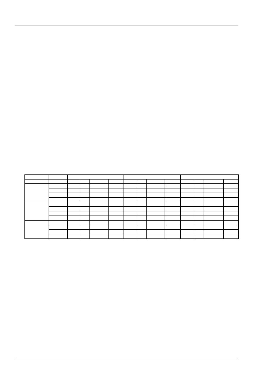
Code_Aster
®
Version
6.4
Titrate:
Postprocessing according to RCC-M'S
Date:
03/03/03
Author (S):
J.M. PROIX
Key
:
R7.04.03-B
Page
:
28/32
Manual of Reference
R7.04 booklet: Evaluation of the damage
HT-66/02/004/A
6.1.5 Calculation of the amplitudes of stresses for the situations of passage enters
group situations
For each situation of passage of a group with another, one considers the whole of the combinations
(I, J) with I pertaining to the first group (of dimension NR) and J pertaining to the second group (of
dimension M). For each combination,
alt
(I, J) is obtained in the same way that previously.
One still builds a matrix (rectangular) containing all
alt
(I, J), which one associates it
a number of occurrences of the situation of passage.
Indeed, two states of loading are combinable only if they belong to the same situation
or if there is a situation of passage between the groups to which they belong. In it
last case, one will associate combination I, J the number of occurrences of the situation of passage.
If the situation of passage belongs to the one of both groups (what is not excluded has
priori), it is naturally combined with the other situations of this group, then is used for the combination
situations of its group with the situations of the group in relation.
6.1.6 Storage of the amplitudes of stresses for all the combinations
To carry out the calculation of the factor of use, amplitudes of the stresses calculated previously and
the associated numbers of occurrences are stored in a square matrix containing all them
amplitudes of stresses alt except seism, for all the possible combinations of situations (with
interior of each group of situations, and between two groups if there is a situation of passage).
The matrix has as a dimension the sum of the number of situations of all the groups:
Alt
Group 1
Group 2
Group 3
Etat1
…
State J
…
…
…
State L
…
…
.
State N
State NR
Group 1
State 1
Alt
… …… 0 0 0
0………
…
State
I
Alt (I, J)
…
0 0 0
0…… alt (I, N)
…
…
… 0 0 0
0………
…
…
… 0 0 0
0………
…
Group 2
….
…
…
…
…
0 0 0
0
State
K
…
Alt (K, L)
…
0 0 0
0
…
…
…
0 0 0
0
….
SYM
…
0 0 0
0
Group 3
….
…
…
…
…
State
m
… Alt (m, N)
…
…
…
…
State
NR
…
In the table above, one associates value 0 the combinations of states between groups 1 and 2 and
groups 1 and 3, because there is not situation of passage between these groups. On the other hand it in
exist between groups 1 and 3, one thus associates herring barrel combination states of groups 1 and 3
the value of alt.
The number of the states of loading will have to be built starting from the number of situation (single) and of
relative number (1 or 2) of the stabilized state of the situation, to obtain a univocal classification of
states of loading.
In the case of the under-cycles, only the diagonal term is filled.
This matrix is also to build for the values of
(
)
S
J
I
S
alt
,
,
who take into account
seism. There are thus two matrices giving all the possible values of alt.
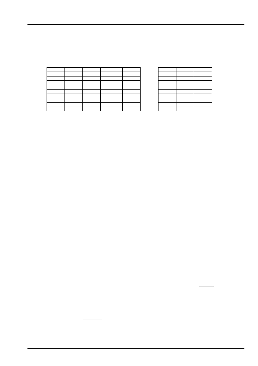
Code_Aster
®
Version
6.4
Titrate:
Postprocessing according to RCC-M'S
Date:
03/03/03
Author (S):
J.M. PROIX
Key
:
R7.04.03-B
Page
:
29/32
Manual of Reference
R7.04 booklet: Evaluation of the damage
HT-66/02/004/A
In correspondence of this matrix, one can associate a table giving the number of occurrences, it
number of situation and the number of group of each stabilized state, and a table giving the number
occurrences of the situations of passage:
State
Situation groups
Under-cycle
nocc
group 1 group 2
Npass
State
1
1 1 0 N1 1 1 0
… 1 1 0 N1 1 2 0
State I
2
1
0
Ni
1
3
npass
… 2 1 0 Ni………
State
K
3 2 0 Nk 2 1 0
… ………… 2 2 0
State
m
… 3
nsous
0 2 3 0
… ………… 3 1
npass
State NR
NR
3
0
NR
…
…
…
6.2
Calculation of the factor of use
For the whole of the combinations of states of loading (inside a group of situations or
associated a situation of passage), and for each end of the segment:
The general step described by the §ZH210 of code RCC-M is as follows:
One considers the whole of the NR stabilized states, and one builds:
·
the matrix [NR, NR] of the equivalent amplitudes of stress
alt
(I, J, T, S) corresponding to
superposition of the transient of passage of the state stabilized I in a state stabilized J, of the transient
thermics associated and with the seismic loading.
·
the matrix [NR, NR] of the equivalent amplitudes of stress
alt
(I, J, T) corresponding to
superposition of the transient of passage of the state stabilized I in a state stabilized J and of the transient
associated thermics (without seism).
One notes:
N
K
the number of cycles associated with the situation p to which belongs the state stabilized K;
N
L
the number of cycles associated with the situation Q to which belongs the state stabilized L;
NR
S
the number of occurrences of the seism (in general only of SNA is considered in second
category)
N
S
a number of under-cycles associated with each seism.
N
not
a number of cycles associated with a possible situation with passage between p and Q if these
situations do not belong to the same group, but if there is a situation of
passage enters both.
If NR
S
0, one select the NS/2 combinations more penalizing, i.e. the NS/2
combinations (K, L) driving with the greatest values of
alt
(K, L), without taking into account it
seism.
For each of these NS/2 combinations:
·
One calculates the factor of use U
1
(K, L) associated
alt
(I, J, T, S):
()
()
L
K
NR
L
K
U
,
1
,
1
=
, with NR (K, L) it
a number of acceptable cycles associated
alt
(I, J, T, S).
·
One takes into account N
S
under-cycles of the seism by:
()
L
K
S
SC
alt
,
'
_
, K and L being both
extreme states of the under-cycle. Then:
() (
)
()
L
K
NR
N
L
K
U
SC
S
,
1
.
2
,
2
-
=
with NR
SC
(K, L) a number of acceptable cycles for the amplitude of
stress
alt_SC
(K, L).

Code_Aster
®
Version
6.4
Titrate:
Postprocessing according to RCC-M'S
Date:
03/03/03
Author (S):
J.M. PROIX
Key
:
R7.04.03-B
Page
:
30/32
Manual of Reference
R7.04 booklet: Evaluation of the damage
HT-66/02/004/A
·
One obtains then: U (K, L) = U
1
(K, L) + U
2
(K, L)
·
One starts again this calculation until exhaustion of the NS/2 combinations more penalizing.
The calculation of the factor of use is then continued without taking into account the seism:
If NR
S
= 0, or after having taken into account the seism for the NS/2 combinations more
unfavourable:
·
One selects the combination (K, L) leading to the maximum value of
alt
(K, L), on
the whole of the combinations, such as the number of occurrences N
0
that is to say not no one.
With N
0
= min {N
K
, N
L,
, N
not,
} if N
not
is nonnull, or N
0
= min {N
K
, N
L,
} if N
not
is null.
·
one calculates the number of acceptable cycles NR (K, L) for the amplitude of stress
alt
(K, L).
NR (K, L) corresponds to the X-coordinate of the point of ordinate
alt
(K, L) in the curve of Wöhler
associated material.
·
One calculates the factor of use U (K, L) associated the amplitude of stress
alt
(K, L):
()
()
L
K
NR
N
L
K
U
,
,
0
=
·
One increments the factor of total use: U = U + U (K, L)
·
One replaces:
N
K
by (N
K
- N
0
)
N
L
by (N
L
- N
0
)
if it is about a situation of passage, N
not
by (N
not
- N
0
)
if N
K
= 0, the column and the line K of the matrix of
alt
(I, J) are put at 0.
if N
L
= 0, the column and the line L of the matrix of
alt
(I, J) are put at 0.
·
The loop is repeated until complete exhaustion of the number of cycles.
Note:
Appendix ZI of code RCC-M defines the curve of Wöhler until an amplitude of
stress minimum corresponding to one lifespan of 10
6
cycles. If the value
alt
calculated for a combination (I, J) of stabilized state is lower than this amplitude
minimum, the factor of use is equal to 0 for the combination (I, J) considered.
The loop is repeated until exhaustion of the number of cycles.
The factor of use
G
U
of each end of the segment for the group considered is then defined by:
()
=
L
K
U
U
G
,
. It is cumulated with the factor of total use:
G
early
early
U
U
U
+
=

Code_Aster
®
Version
6.4
Titrate:
Postprocessing according to RCC-M'S
Date:
03/03/03
Author (S):
J.M. PROIX
Key
:
R7.04.03-B
Page
:
31/32
Manual of Reference
R7.04 booklet: Evaluation of the damage
HT-66/02/004/A
7 Bibliography
[1]
“RCC-M: Rules of Design and Construction of the mechanical hardware of the small islands
nuclear PWR. Edition 1991 “Published by the AFCEN: French association for the rules of
design and of construction of the hardware of the nuclear boilers.
[2]
Y. WADIER, J.M. PROIX, “Specifications for an ordering of Aster allowing of
analyzes according to rules' of the RCC-M B3200 “. Note EDF/DER/HI-70/95/022/0 “RCC-M:
Rules of Design and Construction of the mechanical hardware of the nuclear small islands
PWR. Edition 1993 “Published by the AFCEN: French association for the rules of design
and of construction of the hardware of the nuclear boilers.
[3]
I. BAKER, K. AABADI, A.M. DONORE: “Project OAR: Description of “file OAR”,
filing system of fuel supply of the data base “Notes EDF/R & D/HI-75/01/008/C
[4]
F. CURTIT “Realization of a software tool for analysis to fatigue for a line of piping -
schedule of conditions “Notes EDF/R & D/HT-26/02/010/A
[5]
F. CURTIT “Analyzes with the fatigue of an interior line VVP Br with under-thickness” Notes
EDF/R & D/HT-26/00/057/A

Code_Aster
®
Version
6.4
Titrate:
Postprocessing according to RCC-M'S
Date:
03/03/03
Author (S):
J.M. PROIX
Key
:
R7.04.03-B
Page
:
32/32
Manual of Reference
R7.04 booklet: Evaluation of the damage
HT-66/02/004/A
Intentionally white left page.