
Code_Aster
®
Version
6.3
Titrate:
Note of use of the elements plates and hulls
Date:
21/06/02
Author (S):
A. ASSIRE, P. MASSIN, F. LEBOUVIER
Key
:
U2.02.01-A
Page
:
1/50
Instruction manual
U2.02 booklet: Elements of structure
HT-66/02/003/A
Organization (S):
EDF/AMA, DeltaCAD
Instruction manual
U2.02 booklet: Elements of structure
Document: U2.02.01
Note of use of the elements plates and hulls
Summary:
This document is a note of use for modelings plates and hulls.
The elements of hulls and plates play a part in the numerical modeling of the mean structures with
surface average, planes (modeling plates) or curve (modeling hulls).
They are usable in or not linear linear mechanics and thermics.

Code_Aster
®
Version
6.3
Titrate:
Note of use of the elements plates and hulls
Date:
21/06/02
Author (S):
A. ASSIRE, P. MASSIN, F. LEBOUVIER
Key
:
U2.02.01-A
Page
:
2/50
Instruction manual
U2.02 booklet: Elements of structure
HT-66/02/003/A
Count
matters

Code_Aster
®
Version
6.3
Titrate:
Note of use of the elements plates and hulls
Date:
21/06/02
Author (S):
A. ASSIRE, P. MASSIN, F. LEBOUVIER
Key
:
U2.02.01-A
Page
:
3/50
Instruction manual
U2.02 booklet: Elements of structure
HT-66/02/003/A

Code_Aster
®
Version
6.3
Titrate:
Note of use of the elements plates and hulls
Date:
21/06/02
Author (S):
A. ASSIRE, P. MASSIN, F. LEBOUVIER
Key
:
U2.02.01-A
Page
:
4/50
Instruction manual
U2.02 booklet: Elements of structure
HT-66/02/003/A
1 Introduction
The elements of hulls and plates are particularly used to modelize structures
thin where the relationship between dimensions (characteristic thickness/length) is much lower than
1/10 (thin hulls) or about 1/10 (thick hulls).
These modelings are usable in linear and nonlinear mechanics, under assumption of
small deformations and small displacements or many assumptions of great displacements and of
great rotations, according to modelings. A mean modeling of hull is also
available in transitory linear thermics.
Two categories of thin elements of structures are described in this document:
·
The elements of plates, which are plane, therefore the curvature of the structure to be represented is not
ideally not taken into account and it is necessary to use a great number of elements of
way to approach correctly the geometry of the structure (aspect breakages).
·
The elements of hulls, which are curved, therefore the geometry of the structure is better
approached.
Concerning the nomenclature and the reference materials associated with each one of
modelings:
·
the plane elements of plates triangle and quadrangle are gathered under modelings,
(reference material [R3.07.03]):
-
DKT: net TRIA3 element DKT, mesh QUAD4 elements DKQ (linear geometrical);
-
DST: net TRIA3 DST element, mesh QUAD4 element DSQ (linear geometrical);
-
Q4G: net QUAD4 element Q4G (linear geometrical);
·
the elements of curved hulls resulting from models 3D with a kinematics of hull are
gathered under modelings:
-
COQUE_3D: net TRIA7 and QUAD9, structure 3D with unspecified geometry ([R3.07.04]
into linear geometrical, [R3.07.05] into linear geometrical and [R3.03.07] with
following pressures);
-
COQUE_AXIS: net SEG3, hulls with symmetry of revolution around the axis
0Y ([R3.07.02] into linear geometrical);
-
COQUE_C_PLAN or COQUE_D_PLAN: net SEG3, hulls with invariant geometry it
length of axis OZ ([R3.07.02] into linear geometrical).
A characteristic: for studies on reinforced concrete structures, elements of plates
specific were developed to represent the tablecloths of reinforcement made up of two
metal reinforcements with 90° one compared to the other (the most general case for the concrete structures
armed). They are elements of orthotropic plates DKT to 3 nodes offset compared to the layer
means out of concrete. This last is modelized by elements of plates DKT or DST with 3 nodes. One
for the tablecloths of reinforcement a modeling defines ROASTS which uses the elements of plates DKT
with 3 usual nodes. The reinforced concrete structure is then represented by the superposition of
modelings ROASTS and of that used for the concrete (DKT or DST).
Code_Aster
®
Version
6.3
Titrate:
Note of use of the elements plates and hulls
Date:
21/06/02
Author (S):
A. ASSIRE, P. MASSIN, F. LEBOUVIER
Key
:
U2.02.01-A
Page
:
5/50
Instruction manual
U2.02 booklet: Elements of structure
HT-66/02/003/A
2 Mechanics
2.1
Capacities of modeling
2.1.1 Recall of the formulation
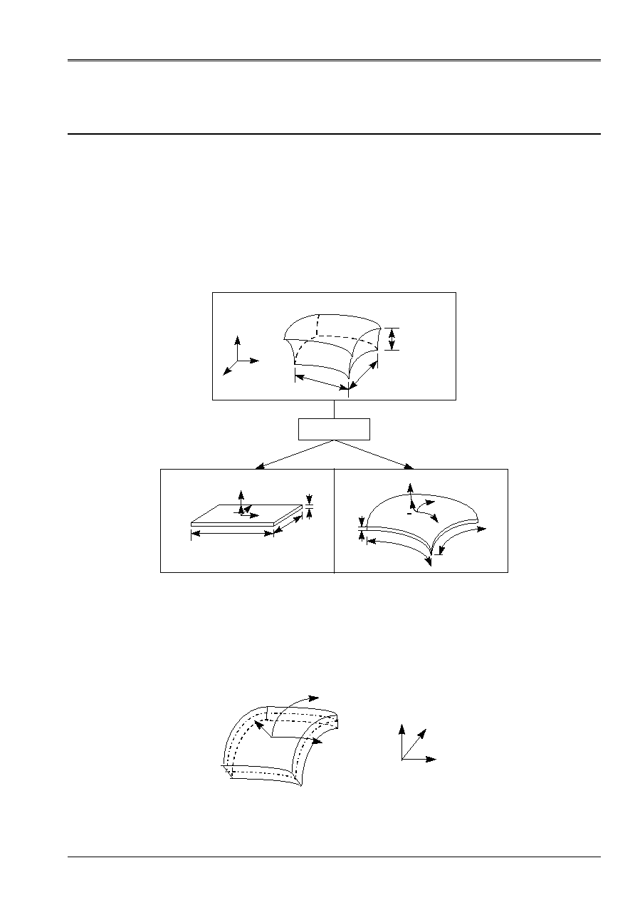
2.1.1.1 Geometry of the elements plates and hulls
For the elements plates and hulls one defines a surface of reference, or surfaces average, plane
(plan X y for example) or curve (X and define a whole of curvilinear co-ordinates in it) and one
thickness H (X, y). This thickness must be small compared to other dimensions of the structure with
to modelize. The figure below illustrates these various configurations.
Thickness H < L, B
Solid 3D
X
Y
Z
H
L
B
Plate
L
B
H
X
y
Z
N
Hull
Z
X
y
N
L
B
H
Appear 2.1.1.1-a: Assumption in theory of the plates and hulls
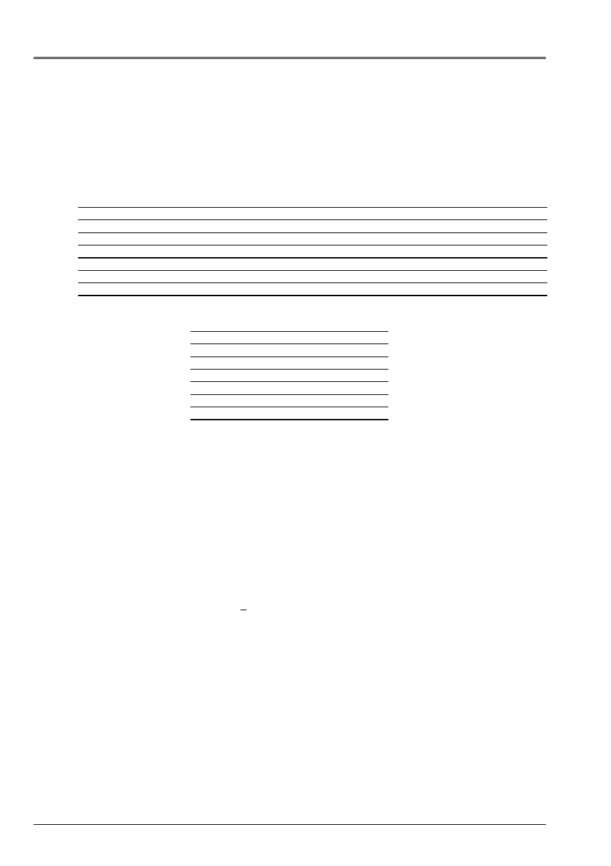
One attaches to average surface
a local reference mark Oxyz different from total reference mark OXYZ. The position
points of the plate or hull is given by the curvilinear co-ordinates (
1
,
2
) of surface
average and front elevation
3
compared to this surface. For the plates the frame of reference
curvilinear is a local Cartesian frame of reference.
O
Y
Z
N,
3
2
X
1
, X
, y
, Z
_
Appear 2.1.1.1-b: Definition of an average surface
Code_Aster
®
Version
6.3
Titrate:
Note of use of the elements plates and hulls
Date:
21/06/02
Author (S):
A. ASSIRE, P. MASSIN, F. LEBOUVIER
Key
:
U2.02.01-A
Page
:
6/50
Instruction manual
U2.02 booklet: Elements of structure
HT-66/02/003/A
To represent hulls with symmetry of revolution around an axis (COQUE_AXIS) or hulls
with invariant geometry by translation (COQUE_C_PLAN in plane stresses or COQUE_D_PLAN in
plane deformations), the knowledge of the section of revolution or the trace of surface
average is sufficient, as the figure [Figure 2.1.2.1-a] shows it to us. These hulls rest on
a linear mesh and in a point
m
average surface one defines a local reference mark (
N
,
T
,
E
Z
)
by:
T
= Om
, S
Om
, S
;
N
T = E
Z
.
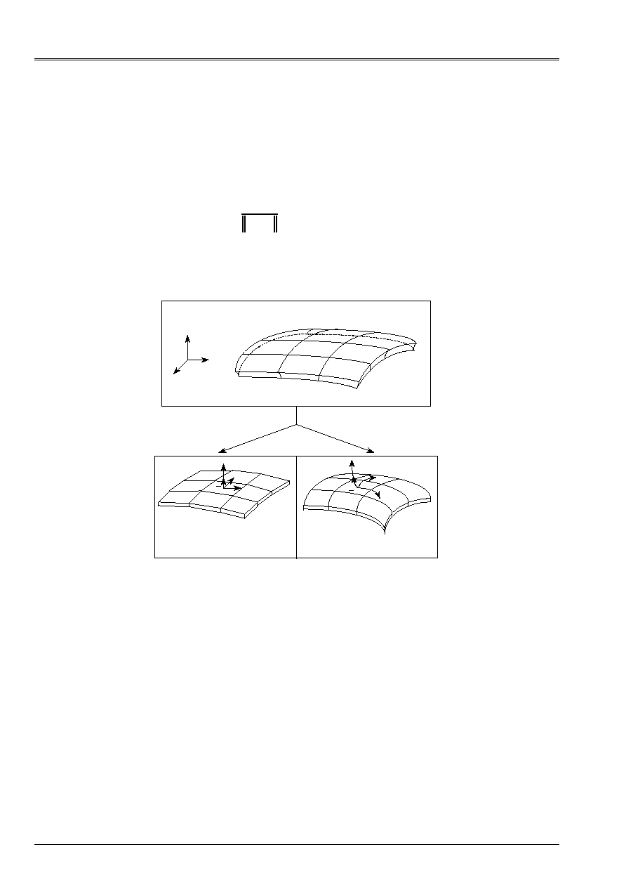
When one wishes to modelize a solid of an unspecified form (not plan), one can use
elements of hulls to account for the curvature, or many elements of plates. In it
last case, the geometry is approximated by a network of breakages.
Solid complete 3D
X
Y
Z
Elements of plates: breakages
X
y
Z
N
X
y
Z
N
Elements of hulls
Z
X
y
N
Z
X
y
N
Appear 2.1.1.1-c: Modeling of an unspecified solid 3D by elements of plates or hulls

Code_Aster
®
Version
6.3
Titrate:
Note of use of the elements plates and hulls
Date:
21/06/02
Author (S):
A. ASSIRE, P. MASSIN, F. LEBOUVIER
Key
:
U2.02.01-A
Page
:
7/50
Instruction manual
U2.02 booklet: Elements of structure
HT-66/02/003/A
2.1.2 Formulation of the elements plates and hulls
2.1.2.1 Formulation into linear geometrical
In this formulation, one supposes that displacements are small, one can thus superimpose
initial geometry and deformed geometry. These elements are based on the theory of the plates according to
which:
·
the cross-sections which are the sections perpendicular to the surface of reference remain
straight lines; material points located on a normal at not deformed average surface
remain on a line in the deformed configuration. It results from this approach that them
fields of displacement vary linearly in the thickness of the plate or of
hull. If one indicates by U, v and W displacements of a point Q (X, y, Z) according to X, y and Z, one
has as follows:
+
=
0
)
y
,
X
(
)
y
,
X
(
Z
)
y
,
X
(
W
)
y
,
X
(
v
)
y
,
X
(
U
)
Z
,
y
,
X
(
W
)
Z
,
y
,
X
(
v
)
Z
,
y
,
X
(
U
y
X
The associated tensor of deformation is written then:
)
y
,
X
(
Z
)
y
,
X
(
)
y
,
X
(
)
Z
,
y
,
X
(
E
+
+
=
.
first term E includes/understands the deformations of membrane (for an element of plate it
are the deformations in the plan of the element), the second
those of shearing
transverse, and third Z
deformations of bending, associated the tensor of
curvature
. For the thick plates or hulls transverse shearings are taken
in account following the formulation suggested by Reissner, Hencky, Bollé, Mindlin. This
formulation includes the approach without transverse shearing, where the tensor
is null,
developed by Kirchhoff for the thin plates or hulls according to which points
hardware located on a normal N at not deformed average surface remains on
normal on the deformed surface.
·
the transverse stress
zz
bus is null regarded as negligible compared to
other components of the tensor of the stresses (assumption of the plane stresses).
·
one does not describe the variation thickness nor that of the transverse deformation
zz
that one
can calculate by using the preceding assumption of plane stresses.
·
the taking into account of transverse shearing depends on given factors of correction has
priori by energy equivalences with models 3D, so that rigidity
in transverse shearing of the model of plate is nearest possible to that defined
by the theory of three-dimensional elasticity. For the homogeneous plates, the factor of
transverse correction of shearing based on this method is k=5/6.
Note:
The determination of the factors of correction rests for Mindlin on equivalences of
Eigen frequency associated the mode of vibration by transverse shearing. One obtains then
K =
2
12
/
, value very close to 5/6.
Code_Aster
®
Version
6.3
Titrate:
Note of use of the elements plates and hulls
Date:
21/06/02
Author (S):
A. ASSIRE, P. MASSIN, F. LEBOUVIER
Key
:
U2.02.01-A
Page
:
8/50
Instruction manual
U2.02 booklet: Elements of structure
HT-66/02/003/A
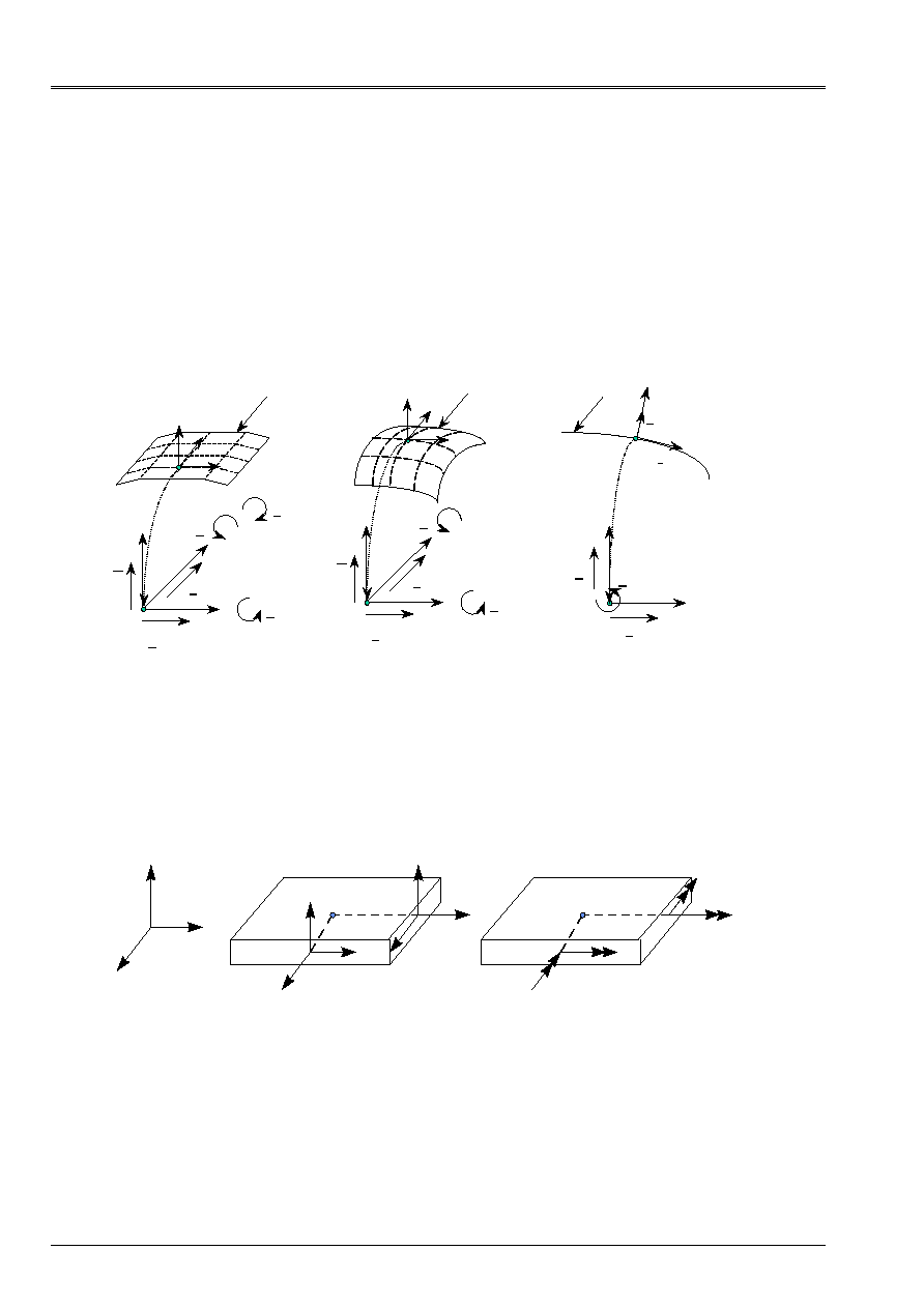
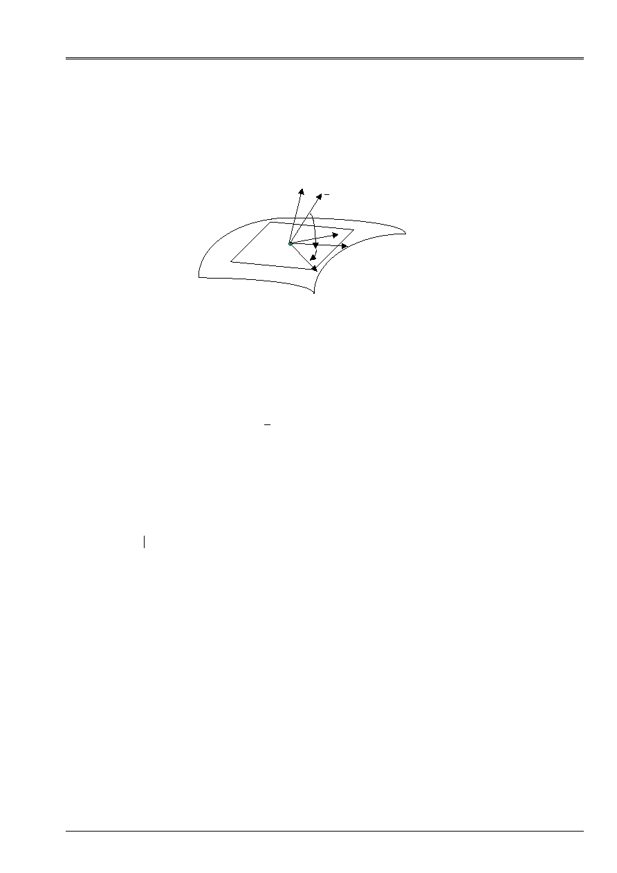
These elements utilize locally:
·
five variables kinematics for the elements plates and hulls unspecified;
displacements of membrane U and v in the datum-line z=0, transverse displacement
W and rotations
X
and
y
normal on the average surface in the yz plans and xz
respectively.
·
three variables kinematics for the linear elements; displacements U and v in
datum-line z=0 and rotation
N
normal on the average surface in the xy plan.
Surface average
Trace average surface
Plane elements or of plates
Curved elements or of hulls
Linear elements for the hulls
invariant by translation
and axisymmetric hulls
X
y
Z
U
v
W
X
y
X
y
Z
U
v
W
X
y
X
y
Z
X
y
X
y
U
v
N
N
y
Average plan
X
y
Z
Average plan
X
y
Z
T
Appear 2.1.2.1-a: Variables kinematics for the various elements of plates and hulls
·
three efforts resulting from membrane noted Nxx, Nyy, Nxy and three noted moments bending
Mxx, Myy, Mxy whatever the element of plate or hull; two noted sharp efforts
Vx and Vy in the case of elements of plates and unspecified hulls.
y
Z
X
NR
xx
NR
xy
V
X
P
NR
yy
V
y
NR
yx
M
xy
M
xx
P
M
yx
M
yy
Appear 2.1.2.1-b: Efforts resulting for an element from plate or hull

Code_Aster
®
Version
6.3
Titrate:
Note of use of the elements plates and hulls
Date:
21/06/02
Author (S):
A. ASSIRE, P. MASSIN, F. LEBOUVIER
Key
:
U2.02.01-A
Page
:
9/50
Instruction manual
U2.02 booklet: Elements of structure
HT-66/02/003/A
2.1.2.2 Formulation into non-linear geometrical, Buckling of Euler
In the formulation into non-linear geometrical, one is in the presence of great displacements and of
great rotations, one cannot superimpose the initial geometry and the deformed geometry.
The formulation, described in the reference material [R3.07.05], is based on an approach of
continuous medium 3D, degenerated by the introduction of the kinematics of hull of the type
Hencky-Mindlin-Naghdi in plane stresses in the weak formulation of balance. The measurement of
deformations selected is that of Green-Lagrange, vigorously combined with the stresses of
Piola-Kirchhoff of second species. The formulation of balance is thus a formulation
Lagrangian total. Transverse shearing is treated same manner as in the case
linear [R3.07.04].
The element retained into non-linear is a voluminal element of hull (COQUE_3D) of average surface
curve as presented at the preceding paragraph, whose meshs supports are QUAD9 and
TRIA7.
It is possible to apply to these elements of the following pressures, whose formulation is described
in the reference document [R3.03.07]. This loading with the characteristic to follow the geometry of
the structure during its deformation (for example, the hydrostatic pressure always remains
perpendicular with the deformed geometry).
Linear buckling also called buckling of Euler, described in the reference material
[R3.07.05], is presented in the form of a particular case of the geometrical non-linear problem. It is based
on a linear dependence of the fields of displacements, strains and stresses by
report/ratio on the level of load.
The element retained in linear buckling is the voluminal element of hull (COQUE_3D) of surface
curved average as presented at the preceding paragraph, whose meshs supports are QUAD9
and of the TRIA7.
2.1.3 Comparison enters the elements
2.1.3.1 Differences between the elements plates and hulls
The elements of hull are curved elements whereas the elements of plates are plane.
variation of metric of the geometry (i.e. its radius of curvature) according to sound
thickness is taken into account for the elements of hulls but not for the elements of plates.
This variation of metric implies a coupling between the effects of membrane and bending for
nonplane structures which cannot be observed with elements of plate plan for one
homogeneous material (see [bib1]).
The choice of the functions of form for the discretization of these elements is different bus the elements
curved hulls have a more significant number of degrees of freedom. Thus, elements of plates
are linear elements out of membrane whereas the elements of hulls are quadratic.
2.1.3.2 Differences between the elements plates
One distinguishes the elements with transverse shearing (DST, DSQ and Q4G) from the elements without
transverse shearing (DKT and DKQ). Elements DST and DKT have triangular meshs support with
3 nodes (3x5 =15 ddl) and elements DKQ, DSQ and Q4G of the quadrangular meshs supports to 4
nodes (4x5 =20 ddl).
Important remark:
For the elements of plate with 4 nodes (DSQ, DKQ and Q4G), the 4 nodes must be
coplanar so that the theory of the plates can be validated. This checking is
carried out systematically by Code_Aster, and the user is alarmed if one
elements of the mesh does not observe this condition.
Code_Aster
®
Version
6.3
Titrate:
Note of use of the elements plates and hulls
Date:
21/06/02
Author (S):
A. ASSIRE, P. MASSIN, F. LEBOUVIER
Key
:
U2.02.01-A
Page
:
10/50
Instruction manual
U2.02 booklet: Elements of structure
HT-66/02/003/A
In the case of elements with transverse shearing, to avoid the blocking of the elements in
transverse shearing (over-estimate of rigidity for very low thicknesses), a method
consist in building fields of constant shearing of substitution on the edges of the element,
whose value is the integral of shearing on the edge in question. In Code_Aster, the elements
of plate and hull with transverse shearing use this method in order not to lock
in transverse shearing. This blocking in shearing comes owing to the fact that elastic energy from
shearing is a term proportional to H (H being the thickness of the plate or the hull) much more
large that the elastic term of energy of bending which is proportional out of H
3
. When the thickness
becomes weak in front of the characteristic length (the ratio H/L is lower than 1/20), for some
functions of form, the minimization of the dominating term out of H leads to bad
representation of the modes of pure bending, for which the arrow is not calculated any more correctly
(see [bib1] page 295 with H/L=0.01).
Element Q4G is a quadrilateral element with four nodes without blocking in transverse shearing,
with bilinear functions of form in X and to represent W there,
X
and
y
. It is the same for
elements DST and DSQ. The difference between DSQ and Q4G (DST modeling, [bib1]) comes owing to the fact that
one uses for the latter of the quadratic functions of form to discretize on each edge
rotation
S
in the sz plan where S is the co-ordinate along the sides. Rotation
N
in the nz plan where
N is the normal at the side directed towards the outside of the element remains discretized with functions of
form bilinear (see it [Figure 2.1.3.2-a]).
I (X
I
, y
I
)
J (X
J
, y
J
)
K
Z
N
K
T
K
S
s=0
s=L
K
S
N
Appear 2.1.3.2-a: Element of plate with transverse shearing
2.1.3.3 Differences between the elements hulls
One distinguishes the linear elements of hulls COQUE_C_PLAN, COQUE_D_PLAN and axisymmetric
COQUE_AXIS of the elements of COQUE_3D.
The first are used to modelize invariant structures according to axis OZ or of revolution
of axis OY and seconds in all the other cases. In the case of invariant hulls according to
direction Z, one distinguishes the free hulls in Z (forced plane COQUE_C_PLAN) from the hulls
locked in Z (plane deformations COQUE_D_PLAN). For these elements of hulls, meshs
supports are linear with 3 nodes. The number of degrees of freedom of these elements is 9.

Code_Aster
®
Version
6.3
Titrate:
Note of use of the elements plates and hulls
Date:
21/06/02
Author (S):
A. ASSIRE, P. MASSIN, F. LEBOUVIER
Key
:
U2.02.01-A
Page
:
11/50
Instruction manual
U2.02 booklet: Elements of structure
HT-66/02/003/A
The unspecified elements of hulls COQUE_3D have triangular meshs support with 7 nodes or
quadrangular with 9 nodes:
·
In the case of triangular meshs, the number of degrees of freedom for the translations is 6
(the unknown factors are displacements with the nodes nodes and on the mediums on the sides of
triangle) and that of rotations are the 7 (unknown factors are 3 rotations at the preceding points
and in the center of the triangle). The number of degrees of freedom total of the element is thus of
Nddle=3x6+3x7=39.
·
In the case of quadrangular meshs with 9 nodes, the number of degrees of freedom for
translations is the 8 (unknown factors are displacements with the nodes nodes and on
mediums on the sides of the quadrangle) and that of rotations is the 9 (unknown factors are the 3
rotations at the preceding points and the center of the quadrangle). The number of degrees of freedom
total of the element is thus of Nddle=3x8+3x9=51. These elements thus have about two
time more degrees of freedom than the elements of plate of corresponding family DKT.
Their cost in time, with an equal number, in a calculation will be thus more important.
The elements of COQUE_3D automatically take into account the correction of metric between
surface average and the surfaces upper and lower. For the linear elements, this correction
must be activated by the user (see the paragraph 14). The correction of metric brings one
contribution out of H/L to the stress and in (H/L)
2
in displacement (see [V7.90.03]). For the plates this
correction is without object.
For the elements of hulls the coefficient of correction of shearing K in isotropic behavior
can be modified by the user. This coefficient of correction of shearing is given in
AFFE_CARA_ELEM under key word A_CIS. By defect, if the user does not specify anything in
AFFE_CARA_ELEM that amounts using the theory with shearing of REISSNER; the coefficient of
shearing is then put at k=5/6. If the coefficient of shearing K is worth 1 one places within the framework
theory of HENCKY-MINDLIN_NAGHDI and if it becomes very large (
10
6
H/L) one approaches
the theory of LOVE_KIRCHHOFF.
In practice it is advised not to change this coefficient. Indeed, these elements provide one
physically correct solution, that the hull is thick or thin, with the coefficient K = 5/6.
2.2
Controls to be used
2.2.1 Space discretization and assignment of a modeling
: operator
AFFE_MODELE
In this part, one describes the choice and the assignment of one of modelings plates or hulls thus
that degrees of freedom and associated meshs. The majority of described information are extracted
documentations of use of modelings ([U3.12.01]: Modeling DKT - DST - Q4G,
[U3.12.02]: Modelings COQUE_C_PLAN, COQUE_D_PLAN, COQUE_AXIS).

Code_Aster
®
Version
6.3
Titrate:
Note of use of the elements plates and hulls
Date:
21/06/02
Author (S):
A. ASSIRE, P. MASSIN, F. LEBOUVIER
Key
:
U2.02.01-A
Page
:
12/50
Instruction manual
U2.02 booklet: Elements of structure
HT-66/02/003/A
2.2.1.1 Degrees of freedom
The degrees of freedom of discretization are in each node of the mesh support the components of
displacement with the nodes of the mesh support, except indication.
Modeling
Degrees of freedom (with each node)
Remarks
COQUE_3D
DX DY DZ DRX DRY DRZ
DRX DRY DRZ with the central node the nodes belong to the layer
means of the hull
DKT
DX DY DZ DRX DRY DRZ
The nodes belong to the breakage
tangent with the average layer of the hull
DST
DX DY DZ DRX DRY DRZ
The nodes belong to the breakage
tangent with the average layer of the hull
Q4G
DX DY DZ DRX DRY DRZ
The nodes belong to the breakage
tangent with the average layer of the hull
COQUE_C_PLAN DX DY DRZ
The nodes belong to surface
average of the hull
COQUE_D_PLAN DX DY DRZ
The nodes belong to surface
average of the hull
COQUE_AXIS
DX DY DRZ
The nodes belong to surface
average of the hull
ROAST
DX DY DZ DRX DRY DRZ
The nodes belong to the breakage
tangent with the average layer of the hull.
2.2.1.2 Meshs support of the matrices of rigidity
Modeling Nets
Element
finished
Remarks
COQUE_3D TRIA7
QUAD9
MEC3TR7H
MEC3QU9H
Meshs not presumedly plane
DKT TRIA3
QUAD4
MEDKTR3
MEDKQU4
Plane meshs
DST TRIA3
QUAD4
MEDSTR3
MEDSQU4
Plane meshs
Q4G QUAD4
MEQ4QU4
Plane meshs
COQUE_C_PLAN SEG3 METCSE3 Meshs not presumedly plane
COQUE_D_PLAN SEG3 METDSE3 Meshs not presumedly plane
COQUE_AXIS SEG3
MECXSE3 Meshs not presumedly plane
ROAST TRIA3
MEGRDKT
Plane meshs
Modeling ROASTS used to modelize the reinforced concrete structures has the same ones
characteristics of mesh that modeling DKT with triangles. For the moment, this modeling
is available only for mesh TRIA3.
Note:
In a mesh, to transform meshs TRIA7 into meshs QUAD9, one can use
operator MODI_MAILLAGE.

Code_Aster
®
Version
6.3
Titrate:
Note of use of the elements plates and hulls
Date:
21/06/02
Author (S):
A. ASSIRE, P. MASSIN, F. LEBOUVIER
Key
:
U2.02.01-A
Page
:
13/50
Instruction manual
U2.02 booklet: Elements of structure
HT-66/02/003/A
2.2.1.3 Meshs support of the loadings
All the loadings applicable to the breakages of the elements used here are treated by discretization
direct on the mesh support of the element in displacement formulation. Pressure and other forces
surface as well as gravity are examples of loadings applying directly to
breakages. No special mesh of loading is thus necessary for the faces of the elements
plates and hulls.
For the applicable loadings on the edges of the elements, one a:
Modeling Nets
Element
finished
Remarks
COQUE_3D SEG3
MEBOCQ3
DKT SEG2
MEBODKT
DST SEG2
MEBODST
Q4G SEG2
MEBOQ4G
COQUE_C_PLAN POI1
Meshs support stub to 1 point
COQUE_D_PLAN POI1
Meshs support stub to 1 point
COQUE_AXIS POI1
Meshs support stub to 1 point
ROAST
Forces distributed, linear, of traction, shearing, the bending moments applied to
edges of structures hull are included in this category of loadings.
2.2.1.4 Model
:
AFFE_MODELE
The assignment of modeling passes through operator AFFE_MODELE [U4.41.01].
AFFE_MODELE
Remarks
AFFE
PHENOMENON:
“MECHANICAL”
MODELING “COQUE_3D”
“DKT”
“DST”
“Q4G”
“COQUE_C_PLAN”
“COQUE_D_PLAN”
“COQUE_AXIS”
“GRID”
Note:
It is advisable to check the number of affected elements.
Code_Aster
®
Version
6.3
Titrate:
Note of use of the elements plates and hulls
Date:
21/06/02
Author (S):
A. ASSIRE, P. MASSIN, F. LEBOUVIER
Key
:
U2.02.01-A
Page
:
14/50
Instruction manual
U2.02 booklet: Elements of structure
HT-66/02/003/A
2.2.2 Elementary characteristics: AFFE_CARA_ELEM
In this part, the operands characteristic of the elements of plates and hulls are described.
The documentation of use of operator AFFE_CARA_ELEM is [U4.42.01].
AFFE_CARA_ELEM COQUE_3D
DKT
DST
Q4G
COQUE_C_PLAN
COQUE_D_PLAN
COQUE_AXIS
HULL
·
·
·
·
·
THICK
· · · ·
·
ANGL_REP
· · · ·
A_CIS
·
·
COEF_RIGI_DRZ
· · · ·
·
OFFSETTING
·
·
·
INER_ROTA
·
·
·
MODI_METRIQUE
·
·
AFFE_CARA_ELEM
ROAST
ROAST
·
THICK
·
ANGL_REP ·
OFFSETTING
·
ANGL_L
·
POUR_CENT_L
·
POUR_CENT_T
·
SECTION_L ·
The allocatable characteristics on the elements of plate or hull are:
·
the thickness
THICK
constant on each mesh, since the mesh represents only it
average layer.
·
the coefficient of correction of transverse shearing
A_CIS
for the curved hulls
isotropic.
·
the taking into account of the correction of metric
MODI_METRIQUE
between average surface
and surfaces upper and lower (effective only for the COQUE_C_PLAN,
COQUE_D_PLAN, COQUE_AXIS).
·
a direction of reference D defined by two nautical angles given in the total reference mark,
by the key word
ANGL_REP
. The projection of this direction of reference on the tangent level to
the hull fixes X1, the first direction of the local reference mark. The normal in the tangent plan in fixed one
second and the vector product of the two associated vectors makes it possible to define the local trihedron.
necessary to the supply of the characteristics nonisotropic material and for the analysis of the efforts
generalized, of the state of stress or the generalized and three-dimensional deformations.
The user will have to take care that the selected reference axis is not found parallel with
normal of certain meshs of the mesh. By defect, this direction of reference is axis X
total reference mark of definition of the mesh.
·
a functionality of DEFI_GROUP makes it possible to create a group of meshs automatically
of which it normal is included/understood in a given solid angle, of axis direction of reference.
This control can be used in preprocessing to affect data material not
isotropic or in postprocessing after a calculation of hull.
Code_Aster
®
Version
6.3
Titrate:
Note of use of the elements plates and hulls
Date:
21/06/02
Author (S):
A. ASSIRE, P. MASSIN, F. LEBOUVIER
Key
:
U2.02.01-A
Page
:
15/50
Instruction manual
U2.02 booklet: Elements of structure
HT-66/02/003/A
·
offsetting (constant for all the nodes of the mesh)
OFFSETTING
of each one
they compared to the mesh support. This distance is measured on the normal of the mesh
support. In the excentré case inertias of rotation are obligatorily taken into account
and
INER_ROTA
is put at
YES
.
plan
tangent
X
D
Z
y
X
1
The total xy plan is not
parallel in the tangent plan
Appear 2.2.2-a: Identifies total and plane tangent
For modeling ROASTS, the following geometrical data are necessary to modelize them
tablecloths of reinforcements (see [3]):
·
offsetting (constant for all the nodes of the mesh)
OFFSETTING
of each one
they compared to the mesh support. This distance is measured on the normal of the mesh
support which, in practice, is superposable with that of the concrete.
·
direction of reference D defined previously by
ANGL_REP
.
·
direction of the reinforcements compared to the X1 vector of the tangent plan. One of the directions
ANGL_L
is enough because the grid consists of orthogonal reinforcements between them.
·
percentages of section of reinforcement in direction 1
POUR_CENT_L
and direction 2
POUR_CENT_T
who is orthogonal for him.
·
the sum of the sections of reinforcements per unit of width in direction 1
SECTION_L
.
Important remark:
Orientation of the elements of plates and hulls
The direction of the normals to each element is a recurring problem concerning the use of this type
of element, for example when loadings of the pressure type are applied, or to define
a offsetting or a local reference mark.
By defect for the surface elements the orientation is given by the vector product 12^13 for
a triangle numbered 123 (DKT,…) or 1234567 (COQUE_3D) and 12^14 for a numbered quadrangle
1234 (DKQ,…) or 123456789 (COQUE_3D). For linear hulls N is given by the formula of
paragraph 2.1.1.1 with T directed in the direction of course of the mesh on the level of the mesh.
Generally, these data are accessible while looking in the file from mesh, which is not
very practical for the user. Moreover it is necessary that it checks the coherence of its mesh and to ensure itself
that all the meshs have the same orientation well.

Code_Aster
®
Version
6.3
Titrate:
Note of use of the elements plates and hulls
Date:
21/06/02
Author (S):
A. ASSIRE, P. MASSIN, F. LEBOUVIER
Key
:
U2.02.01-A
Page
:
16/50
Instruction manual
U2.02 booklet: Elements of structure
HT-66/02/003/A
The user can automatically modify the orientation of the elements of the mesh by imposing one
direction of normal, for a mesh or part of using mesh of modelings of hull
and whatever the type of modeling. The reorientation of the elements is done by the means of
the operator
ORIE_NORM_COQU
control
MODI_MAILLAGE
[U4.12.05]. The principle is it
according to: one defines under
ORIE_NORM_COQU
a direction by the means of a vector and a node
belonging to the group of meshs to be reorientated. If the introduced vector is not in the plan of the mesh
selected by
MODI_MAILLAGE
, one automatically deduces a direction from it from normal obtained
like the vector less given its projection in the field of the mesh. All meshs of the group
related with those initially selected will then have the same orientation of normal
automatically. In addition an automatic checking of the same orientation of the meshs
related is carried out by the means of the operator
VERI_NORM
control
AFFE_CHAR_MECA
[U4.25.01].
2.2.3 Materials
:
DEFI_MATERIAU
The definition of the behavior of a material is carried out using operator DEFI_MATERIAU
[U4.43.01].
DEFI_MATERIAU COQUE_3D
DKT
DST
Q4G
COQUE_C_PLAN
COQUE_D_PLAN
COQUE_AXIS
ROAST
COMP. LINEAR
ELAS
· ·
·
·
·
·
ELAS_FO
· ·
·
·
·
·
ELAS_ORTHO
· ·
·
·
ELAS_COQUE
·
·
·
ELAS_COQUE_FO
·
·
·
DEFI_MATERIAU COQUE_3D
DKT
DST
Q4G
COQUE_C_PLAN
COQUE_D_PLAN
COQUE_AXIS
ROAST
COMP. NONLINEAR
TRACTION
· ·
·
ECRO_LINE
· ·
·
ECRO_LINE_FO
· ·
·
CHABOCHE
· ·
·
DEFI_COQU_MULT
·
·
·
DEFI_MATERIAU COQUE_3D
DKT
DST
Q4G
COQUE_C_PLAN
COQUE_D_PLAN
COQUE_AXIS
ROAST
BY LAYER
All comp.
C_PLAN
· ·
·
The materials used with the whole of the elements plates or hulls can have
elastic behaviors in plane stresses whose linear characteristics are constant or
functions of the temperature. The nonlinear behaviors in plane stresses are available
for modelings DKT and hulls. For more information on these nonlinearities one can
to defer to the paragraph [§2.3.2].
The mean composite material structures can be treated currently only by
modelings plates, by using DEFI_COQU_MULT with material characteristics
homogenized. One can also directly introduce the coefficients of rigidity of the matrices of
membrane, bending and shearing with ELAS_COQUE. These coefficients are given in the reference mark
room of the element defined by ANGL_REP. It should be noted that the terms of shearing are not taken in
take into account behavior ELAS_COQUE that for elements DST and Q4G. They are not taken in
take into account elements DKT.
Code_Aster
®
Version
6.3
Titrate:
Note of use of the elements plates and hulls
Date:
21/06/02
Author (S):
A. ASSIRE, P. MASSIN, F. LEBOUVIER
Key
:
U2.02.01-A
Page
:
17/50
Instruction manual
U2.02 booklet: Elements of structure
HT-66/02/003/A
In order to facilitate comprehension, we represented on the figure below the different ones
reference marks used.
X
Y
Z
X ortho
1
4
3
2
X
ortho
Z
ortho
Z
ortho
normal
Skin “SUP”
Skin “INF”
1
3
2
X
ortho
Total reference mark
Identify orthotropism
y
ortho
Z
ortho
X
ortho
y
ortho
Skin MOY'
Stacking
Sleep
Defined layer by layer
Appear 2.2.3-a: Reference marks used for the definition of material
The following example is extracted from case-test SSLS117B and illustrates the syntax of DEFI_COQU_MULT:
MU2=DEFI_COQU_MULT (COUCHE=_F (EPAIS=0.2,
MATER=MAT1B,
ORIENTATION=0.0,),);
In this example, one defines a multi-layer composite thickness 0.2, the material being defines by
MAT1B, and the angle of the 1ère direction of orthotropism (longitudinal direction or direction of fibers) being null. One
will refer to documentation [U4.42.03] for more details concerning the use of
DEFI_COQU_MULT.
2.2.4 Limiting loadings and conditions: AFFE_CHAR_MECA and AFFE_CHAR_MECA_F
The assignment of the loadings and the boundary conditions on a mechanical model is carried out with
the aid of operators AFFE_CHAR_MECA, if loadings and boundary conditions mechanical
on a system are actual values depending on no parameter, or
AFFE_CHAR_MECA_F, if these values are functions of the position or the increment of loading.
The documentation of use of AFFE_CHAR_MECA and AFFE_CHAR_MECA_F is [U4.44.01].

Code_Aster
®
Version
6.3
Titrate:
Note of use of the elements plates and hulls
Date:
21/06/02
Author (S):
A. ASSIRE, P. MASSIN, F. LEBOUVIER
Key
:
U2.02.01-A
Page
:
18/50
Instruction manual
U2.02 booklet: Elements of structure
HT-66/02/003/A
2.2.4.1 List key words factor of AFFE_CHAR_MECA
AFFE_CHAR_MECA COQUE_3D
DKT DST
Q4G
COQUE_C_PLAN
COQUE_D_PLAN
COQUE_AXIS
ROAST
DDL_IMPO
· ·
·
·
·
·
FACE_IMPO
· ·
·
·
·
·
LIAISON_DDL
· ·
·
·
·
·
LIAISON_OBLIQUE
· ·
·
·
·
·
LIAISON_GROUP
· ·
·
·
·
·
CONTACT
· ·
·
·
·
·
LIAISON_UNIF
· ·
·
·
·
·
LIAISON_SOLIDE
· ·
·
·
·
·
LIAISON_ELEM
· ·
·
·
LIAISON_COQUE
· ·
·
·
·
·
FORCE_NODALE
· ·
·
·
·
·
DDL_IMPO
Key word factor usable to impose, with nodes or groups of
nodes, one or more values of displacement.
FACE_IMPO
Key word factor usable to impose, with all the nodes of a definite face
by a mesh or a group of meshs, one or more values of
displacements (or certain associated sizes).
LIAISON_DDL
Key word factor usable to define a linear relation between degrees of
freedom of two or several nodes.
LIAISON_OBLIQUE key Word factor usable to apply, with nodes or groups of
nodes, the same component value of displacement definite per component
in an unspecified oblique reference mark.
LIAISON_GROUP
Key word factor usable to define linear relations between some
degrees of freedom of couples of nodes, these couples of nodes being obtained
while putting in opposite two lists of meshs or nodes.
CONTACT
Key word factor usable to notify conditions of contact and of
friction between two assemblies of meshs.
LIAISON_UNIF
Key word factor allowing to impose the same value (unknown) on
degrees of freedom of a whole of nodes.
LIAISON_SOLIDE
Key word factor allowing to modelize an indeformable part of one
structure.
LIAISON_ELEM
Key word factor which makes it possible to modelize the connections of a hull part with
a beam part or of a hull part with a pipe part (see
paragraph 2.2.4.5).
LIAISON_COQUE
Key word factor making it possible to represent the connection enters of the hulls to
means of linear relations.
FORCE_NODALE
Key word factor usable to apply, with nodes or groups of
nodes, of the nodal forces, definite component by component in
TOTAL reference mark or in an oblique reference mark defined by 3 nautical angles.

Code_Aster
®
Version
6.3
Titrate:
Note of use of the elements plates and hulls
Date:
21/06/02
Author (S):
A. ASSIRE, P. MASSIN, F. LEBOUVIER
Key
:
U2.02.01-A
Page
:
19/50
Instruction manual
U2.02 booklet: Elements of structure
HT-66/02/003/A
AFFE_CHAR_MECA
private individuals
COQUE_3D
DKT DST Q4G
COQUE_C_PLAN
COQUE_D_PLAN
COQUE_AXIS
ROAST
FORCE_ARETE
· ·
·
·
FORCE_COQUE
total
near
tangent room
·
·
·
·
·
·
·
·
·
·
·
·
·
·
·
·
·
·
GRAVITY
· ·
·
· ·
·
PRES_REP
· ·
·
· ·
ROTATION
·
·
TEMP_CALCULEE
· ·
·
· ·
·
EPSI_INIT
·
·
·
·
FORCE_ARETE
Key word factor usable to apply linear forces to an edge
of an element of hull. For the linear elements the equivalent returns to
to apply a nodal force to the nodes supports of the element. There is not thus
no the particular dedicated term. On the other hand, it requires elements of
edges.
FORCE_COQUE
Key word factor usable to apply surface efforts (pressure by
example) on elements defined on all the mesh or one or
several meshs or of the groups of meshs. These efforts can be given
in the total reference mark or a reference mark of reference defined on each
net or groups meshs; this reference mark is built around the normal with
the element of hull and a fixed direction (see paragraph 2.2.2).
GRAVITY
Key word factor usable for a loading of the gravity type.
PRES_REP
Key word factor usable to apply a pressure to one or more
meshs, or of the groups of meshs.
ROTATION
Key word factor usable to calculate the loading due to the rotation of
structure.
TEMP_CALCULEE
Allows to recover the thermal loading resulting from a thermal calculation
linear or not linear. This functionality is useful for the chainings
thermomechanical, not which will be approached in paragraph 4.
EPSI_INIT
Key word factor usable to apply a loading of deformation
initial.
Note:
The efforts of pressure being exerted on the elements of plates can apply is by
FORCE_COQUE (near) is by PRES_REP. The user will have to thus pay attention (in
version 5) not to twice apply the loading of pressure for the elements
concerned, especially whenever modelings of plates would be mixed with
other modelings using PRES_REP.
In addition it should be noted that efforts of pressure, whether it is with FORCE_COQUE (near) or
PRES_REP are such as a positive pressure acts in the contrary direction with that of the normal with
the element. By defect, this normal is dependant on the direction of course of the nodes of an element, it
who is not always very easy for the user. Moreover it is necessary that the aforementioned makes sure that all these
elements are directed same manner. One thus advises to impose the orientation of these
elements by the means of the operator
ORIE_NORM_COQU
control
MODI_MAILLAGE
(see
paragraph [§2.2.2]).

Code_Aster
®
Version
6.3
Titrate:
Note of use of the elements plates and hulls
Date:
21/06/02
Author (S):
A. ASSIRE, P. MASSIN, F. LEBOUVIER
Key
:
U2.02.01-A
Page
:
20/50
Instruction manual
U2.02 booklet: Elements of structure
HT-66/02/003/A
2.2.4.2 List key words factor of AFFE_CHAR_MECA_F
The key words factor Generals of operator AFFE_CHAR_MECA_F are identical to those of
operator AFFE_CHAR_MECA introduced above.
AFFE_CHAR_MECA_F
private individuals
COQUE_3D DKT DST Q4G COQUE_C_PLAN
COQUE_D_PLAN
COQUE_AXIS
ROAST
FORCE_ARETE
· ·
·
·
Total FORCE_COQUE
near
tangent room
·
·
·
·
·
·
·
·
·
·
·
·
·
·
·
·
·
·
The loadings of pressure functions of the geometry can be indicated by the means of
FORCE_COQUE
(near)
.
2.2.4.3 Application of a pressure: key word FORCE_COQUE
The key word factor FORCE_COQUE makes it possible to apply surface efforts to elements of the type
hull
(DKT
,
DST
,
Q4G
,…) defined on all the mesh or one or more meshs or of the groups
meshs. According to the name of the operator called, the values are provided directly
(
AFFE_CHAR_MECA
) or via a concept
function
(
AFFE_CHAR_MECA_F)
.
AFFE_CHAR_MECA
AFFE_CHAR_MECA_F
Remarks
FORCE_COQUE
:
·
ALL:
“YES”
NET
GROUP_MA
·
Place of application of the loading
Identify
total
FX
FY
FZ
MX
MY
MZ
·
Provided directly for
AFFE_CHAR_MECA, in the form of
function for AFFE_CHAR_MECA_F
PLAN “MOY”
“INF”
“SUP”
“MALL”
·
Allows to define a torque of efforts on
the average, lower, higher plan or of
mesh (elements DKT and DST)
Identify
room
CLOSE F1
F2
F3
MF1
MF2
·
Provided directly for
AFFE_CHAR_MECA, in the form of
function for AFFE_CHAR_MECA_F
We return in the paragraph corresponding to key word FORCE_COQUE of the document of use
operators
AFFE_CHAR_MECA
and
AFFE_CHAR_MECA_F
.
2.2.4.4 Limiting conditions: key words DDL_IMPO and LIAISON_ *
The key word factor DDL_IMPO makes it possible to impose, with nodes introduced by one (at least) of the words
keys: ALL, NODE, GROUP_NO, MESH, GROUP_MA, one or more values of displacement (or of
certain associated sizes). According to the name of the operator called, the values are provided
directly (AFFE_CHAR_MECA) or via a concept function (AFFE_CHAR_MECA_F).
The operands available for DDL_IMPO, are listed below:
·
DX DY DZ
Blocking on the component of displacement in translation
·
DRX DRY DRZ
Blocking on the component of displacement in rotation
Code_Aster
®
Version
6.3
Titrate:
Note of use of the elements plates and hulls
Date:
21/06/02
Author (S):
A. ASSIRE, P. MASSIN, F. LEBOUVIER
Key
:
U2.02.01-A
Page
:
21/50
Instruction manual
U2.02 booklet: Elements of structure
HT-66/02/003/A
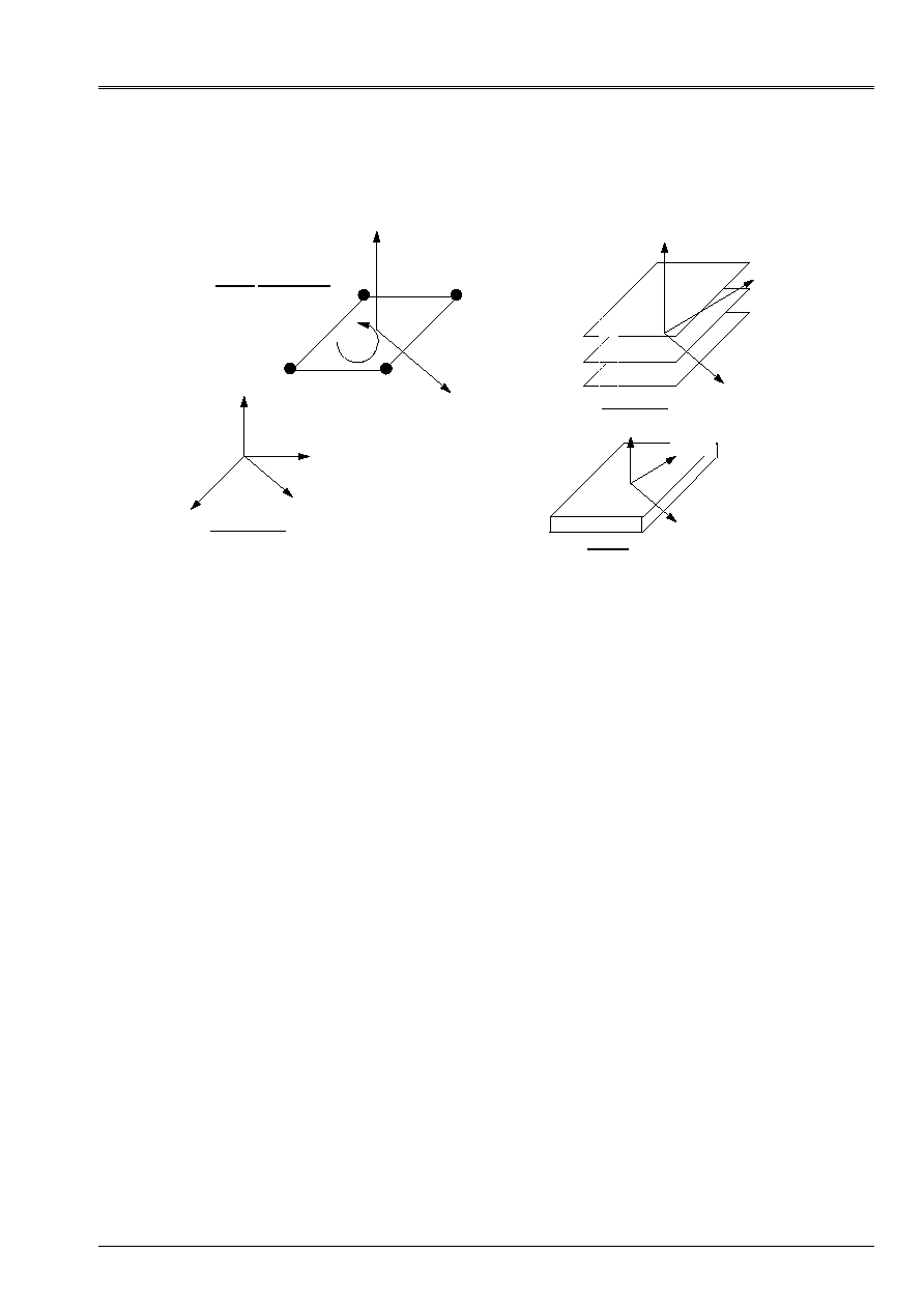
2.2.4.5 Connections hulls with other machine elements
These connections must meet the requirements established in [bib4] and that one finds in particular
in the connection 3d-BEAM in [R3.03.03].
The connections available with the elements of plates and hulls are as follows:
·
Connection Beam-Hull: it is a question of establishing the connection between a node end of an element of
beam and a group of meshs of edge of elements of hulls. Theories of beam and of
plate know only normal cuts with fiber or the average surface.
connections can take place only according to these average fibers or surfaces. The connection
beam-hull is realizable for beams whose neutral fiber is orthogonal with
normals with the breakages of the plates or the hulls. To extend to other configurations
(a beam arriving perpendicular to the plan of a plate for example) request one
feasibility study because the elements of plate or hull do not have rigidity associated with
a rotation in the plan perpendicular to the normal on the average surface. The connection is
usable by using key word LIAISON_ELEM: (OPTION: “COQ_POU”) of
AFFE_CHAR_MECA.
·
Connection Hull-Pipe: it is a question of establishing the connection between a node end of an element of
pipe and a group of mesh of edge of elements of hulls. The formulation of the connection
hull-pipes is presented in the reference document [R3.08.06]. Theories of pipe
and of plate, know only normal cuts with fiber or the average surface.
The connections can take place only according to these average fibers or surfaces. The connection
hull-pipe is realizable for pipes whose neutral fiber is orthogonal with the normals
with the breakages of the plates or hulls. The connection is usable by using the key word
LIAISON_ELEM: (OPTION: “COQ_TUYAU”) of AFFE_CHAR_MECA.
Connection plates or hull - beam
N
N
N normal with the breakage of the hull = tangent to the beam
Connection hull - pipe
Appear 2.2.4.5-a: Connections hulls with other machine elements
·
Connection Hull massive 3D: the connection massive hull-3D is being studied but it will be limited
initially with the cases where the normal with the solid is orthogonal with the normal with the one
breakages of the element of plate or hull (see [bib4]).
·
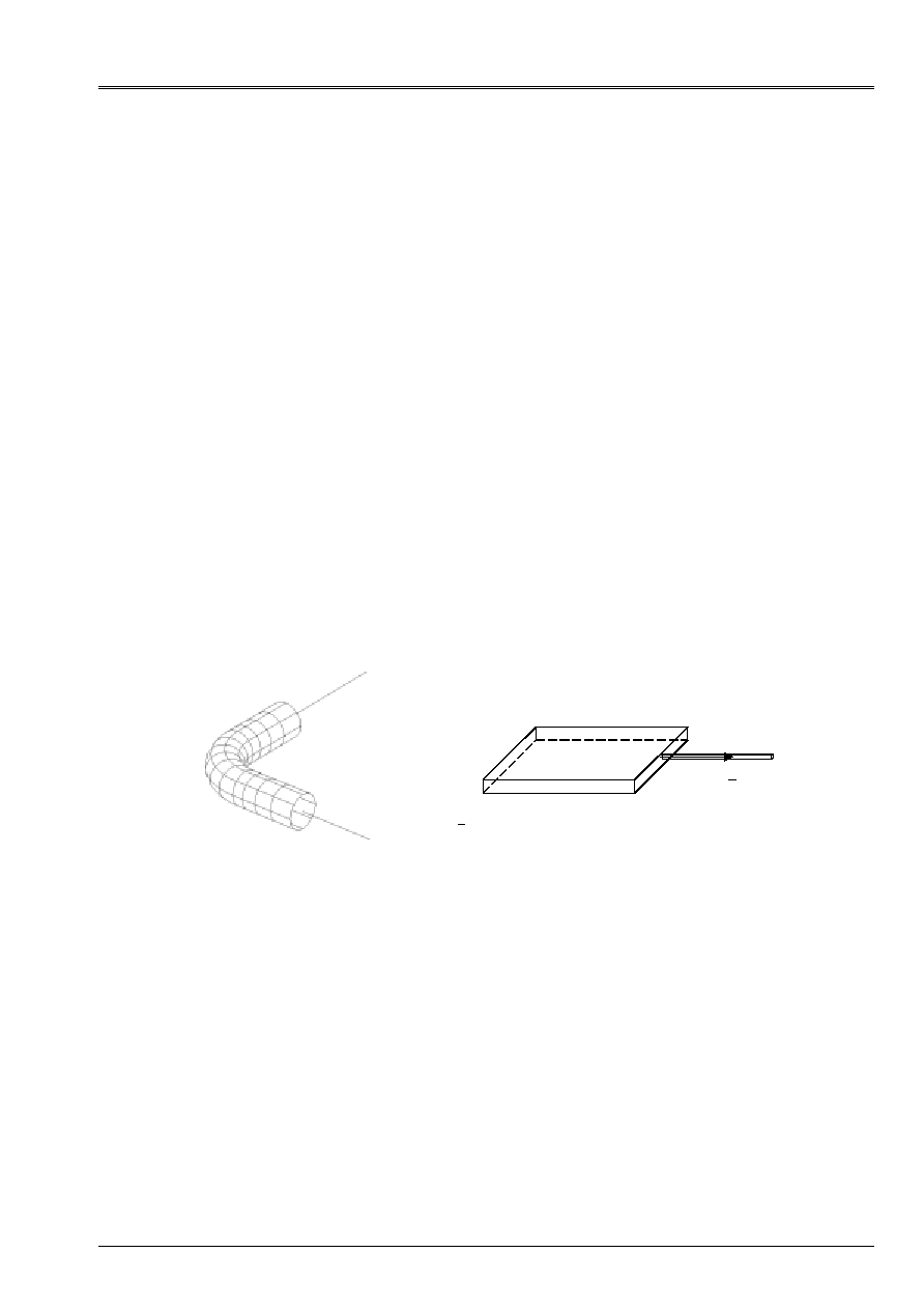
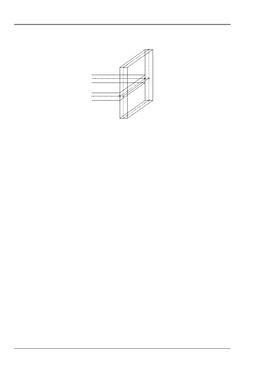
Connection between elements of Hulls: to connect two elements of hulls between them,
one uses key word LIAISON_COQUE of AFFE_CHAR_MECA (_F) (documentation [U4.44.01]).
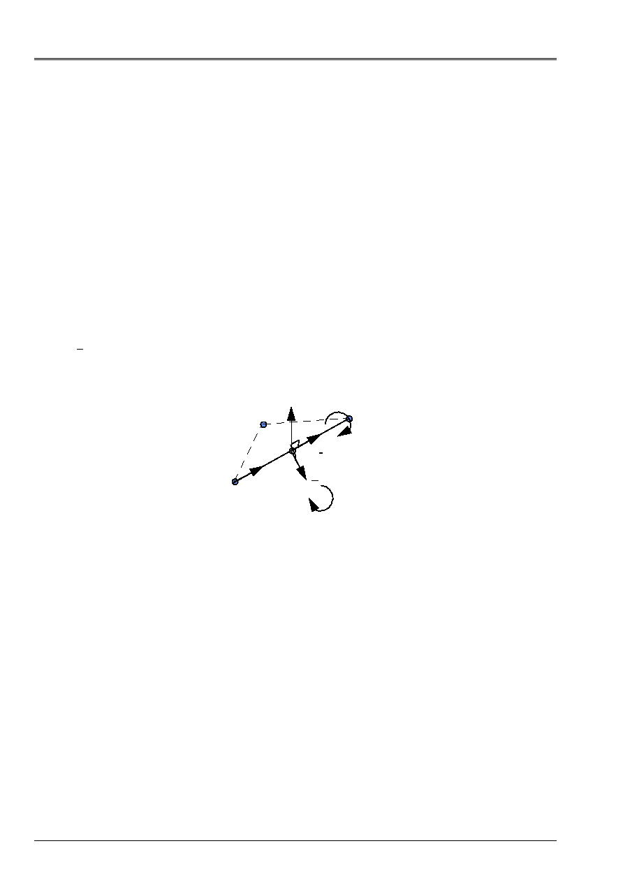
This connection is carried out by means of linear relations. The conventional approach admits that 2
plans with a grid in hulls are cut according to a line which belongs to the mesh of
structure. In order to prevent that the volume which is the intersection of the 2 hulls is counted twice,
one stops the mesh of a hull perpendicular to a hull given to the level of the skin
higher or lower of the latter. On [Figure 2.2.4.5-b], the connection between the 2
hulls is done by connections of solid body between the nodes in with respect to segments A
1
With
2
and B
1
B
2
.
Code_Aster
®
Version
6.3
Titrate:
Note of use of the elements plates and hulls
Date:
21/06/02
Author (S):
A. ASSIRE, P. MASSIN, F. LEBOUVIER
Key
:
U2.02.01-A
Page
:
22/50
Instruction manual
U2.02 booklet: Elements of structure
HT-66/02/003/A
With
1
B
1
B
2
With
2
Appear 2.2.4.5-b: Connection between elements of hulls
Case-tests making it possible to validate these connections are available in the section examples,
2.3 Resolution
2.3.1 Linear calculations: Linear MECA_STATIQUE and other operators
Linear calculations are carried out in small deformations. Several linear operators of resolution
are available:
·
MECA_STATIQUE:
resolution of a problem of static mechanics linear
([U4.51.01]);
·
MACRO_ELAS_MULT:
calculate linear static answers for various cases of
loads or modes of Fourier. ([U4.51.02]).
·
MODE_ITER_SIMULT: calculation of the values and vectors clean by methods of under
spaces. ([U4.52.03]).
·
MODE_ITER_INV:
calculation of the values and vectors clean by the method of iterations
opposite ([U4.52.04]).
·
MODE_ITER_CYCL:
calculation of the clean modes of a structure with cyclic symmetry
([U4.52.05]);
·
DYNA_LINE_TRAN:
calculation of the transitory dynamic response to an excitation
temporal unspecified ([U4.53.02]);
·
DYNA_TRAN_MODAL:
calculation is carried out by modal superposition or by under
structuring ([U4.53.21]);

Code_Aster
®
Version
6.3
Titrate:
Note of use of the elements plates and hulls
Date:
21/06/02
Author (S):
A. ASSIRE, P. MASSIN, F. LEBOUVIER
Key
:
U2.02.01-A
Page
:
23/50
Instruction manual
U2.02 booklet: Elements of structure
HT-66/02/003/A
2.3.2 Nonlinear calculations: STAT_NON_LINE and DYNA_NON_LINE
2.3.2.1 Behaviors and assumptions of deformations available
Following information is extracted from the documentation of use of the operator
STAT_NON_LINE: [U4.51.03].
COQUE_3D DKT DST Q4G COQUE_C_PLAN
COQUE_D_PLAN
COQUE_AXIS
RELATION
All relations
available in stresses
plane
· ·
·
The relations 3D while using:
ALGO_C_PLAN:“DEBORST”
· ·
·
COMP_INCR
(small
deformations)
DEFORMATION:
“GREEN_GR”
Coque_3D into large
displacements and large
rotations available with
incrémentaux behaviors
nonlinear, but into small
deformations
·
RELATION ELAS
DEFORMATION:'
GREEN_GR'
·
COMP_ELAS
(large
deformations)
TYPE_CHARGE:'
SUIV'
Following pressure
·
All the mechanical nonlinear behaviors of plane stresses of the code are accessible.
One distinguishes the incremental relations of behavior (key word factor COMP_INCR) from the relations
nonlinear elastic behaviors (key word factor COMP_ELAS). The relation of behavior
connect the rates of deformation to the rates of stresses.
For modeling ROASTS reinforced concrete structures, the nonlinear behaviors
correspond to particular incrémentaux behaviors in
STAT_NON_LINE
(COMP_INCR)
:
·
GRILL_ISOT_LINE
for plasticity with isotropic work hardening,
·
GRILL_ISOT_CINE
for plasticity with kinematic work hardening linear Bi,
·
GRILL_PINTO_MEN
for the behavior of Pinto Menegotto.
Moreover, the behavior of the average concrete layer is given by a law of the type NADAI_B.
The concept RESULT of STAT_NON_LINE contains fields of displacements, stresses and
variables intern at the points of integration always calculated at the points of gauss:
·
DEPL: fields of displacements.
·
SIEF_ELGA: Tensor of the stresses by element at the points of integration (COQUE_3D and
DKT) in the local reference mark. For each layer, one stores in the thickness and for each
thickness on the points of surface integration. Thus if one wants information on one
stress for layer NC, on level NCN (NCN = - 1 so lower, NCN = 0 if medium, NCN
= +1 so higher) for the surface point of integration NG, it will be necessary to look at the value
data by the point defined in the option NOT such as
: NP = 3 * (NC-
1) * NPG+ (NCN+1) * NPG+NG where NPG is the total number of points of surface integration of
the element of COQUE_3D (7 for the triangle and 9 for the quadrangle) and of element DKT.

Code_Aster
®
Version
6.3
Titrate:
Note of use of the elements plates and hulls
Date:
21/06/02
Author (S):
A. ASSIRE, P. MASSIN, F. LEBOUVIER
Key
:
U2.02.01-A
Page
:
24/50
Instruction manual
U2.02 booklet: Elements of structure
HT-66/02/003/A
·
VARI_ELGA: Field of variables intern (DKT and COQUE_3D) by element at the points
of surface integration. For each point of surface integration, one stores them
information on the layers while starting with the first, level “INF”. The number of
variables represented is worth thus 2 * NCOU * NBVARI where NBVARI represents the number of
internal variables.
It can be enriches by the following fields, calculated in postprocessing by operator CALC_ELEM:
·
SIEF_ELNO_ELGA: activate the calculation of the tensor of the efforts generalized by element with
nodes (membrane efforts, bending moments, sharp efforts), in the reference mark
user (defined in the paragraph [§2.2.2]).
·
VARI_ELNO_ELGA: activate the calculation of the field of internal variables by element with the nodes
in the thickness (by layer SUP/MOY/INF in the thickness except indication).
2.3.2.2 Detail on the points of integration
For non-linear calculations the method of integration for the elements of plate and hulls is
a method of integration by layers, of which the number is defined by the user. For each
sleep, except modeling
ROAST
, one uses a method of Simpson at three points of integration, with
medium of the layer and in skins higher and lower of layer. For NR layers the number of
points of integration in the thickness is of 2N+1.
To treat non-linearities material, one advises to use from 3 to 5 layers in the thickness for
a number of points of integration being worth 7, 9 and 11 respectively. For tangent rigidity, one calculates
for each layer, in plane stresses, the contribution to the matrices of rigidity of membrane, of
bending and of coupling membrane-bending. These contributions are added and assembled to obtain
the matrix of total tangent rigidity. For each layer, one calculates the state of the stresses and
the whole of the internal variables, in the middle of the layer and in skins higher and lower of
sleep. This information is available in VARI_ELGA and SIEF_ELGA. The behavior
plastic does not include/understand the transverse terms of shearing which are treated in an elastic way,
because transverse shearing is uncoupled from the plastic behavior.
For modeling ROASTS reinforced concrete structures, it has only one point of integration there by
sleep.
2.3.2.3 Geometrical non-linear behavior
Calculations into non-linear geometrical (great displacements and great rotations), available with
modeling COQUE_3D, are carried out using operator STAT_NON_LINE, by using it
key word COMP_ELAS, as illustrated in the following example:
STAT_NON_LINE (
COMP_ELAS (RELATION: “ELAS”
COQUE_NCOU: 3
DEFORMATION: “GREEN_GR”)
)
or by using an incremental behavior (key word COMP_INCR) in small deformations.
It is possible to apply to the elements of COQUE_3D, of the following pressures. This loading has
the characteristic to follow the geometry of the structure during its deformation (for example:
hydrostatic pressure remains always perpendicular to the deformed geometry). To take in
count this type of loading, it is necessary to specify in operator STAT_NON_LINE information
following:
STAT_NON_LINE (
EXCIT (LOAD: near
TYPE_CHARGE: “SUIV”)
)

Code_Aster
®
Version
6.3
Titrate:
Note of use of the elements plates and hulls
Date:
21/06/02
Author (S):
A. ASSIRE, P. MASSIN, F. LEBOUVIER
Key
:
U2.02.01-A
Page
:
25/50
Instruction manual
U2.02 booklet: Elements of structure
HT-66/02/003/A
The geometrical non-linear behavior of the structures can have instabilities (buckling,
snap-through/snap-back…). The determination and the passage of these limiting points, cannot be
obtained by imposing the loading, however options of piloting of loading “DDL_IMPO”
or “LONG_ARC” of operator STAT_NON_LINE make it possible to cross these critical points.
2.3.2.4 Buckling
linear
Calculations in linear buckling are similar to the search of Eigen frequencies and modes
of vibration. The problem has to solve is expressed in the form:
To find (
, X)
(R, R
NR
) such as AX=
BX
where A is the matrix of rigidity
B
is the geometrical matrix of rigidity (calculated with option RIGI_GEOM of
CALC_MATR_ELEM)
is the critical load
X is the mode of buckling associated with the critical load
Operators MODE_ITER_INV [U4.52.04] and MODE_ITER_SIMULT [U4.52.03] are used
to determine the critical load and the mode of associated buckling.
2.4
Additional calculations and postprocessings
2.4.1 Elementary calculations of matrices: operator CALC_MATR_ELEM
Operator CALC_MATR_ELEM (documentation [U4.61.01]) allows to calculate matrices
elementary, which is then compilable by control ASSE_MATRICE (documentation
[U4.61.22]).
The elementary options of operator CALC_MATR_ELEM are described below:
CALC_MATR_ELEM COQUE_3D
DKT DST
Q4G
COQUE_C_PLAN
COQUE_D_PLAN
COQUE_AXIS
ROAST
“AMOR_MECA”
· · ·
· ·
·
“MASS_MECA”
· · ·
· ·
·
“RIGI_GEOM”
·
“RIGI_MECA”
· · ·
· ·
·
“RIGI_MECA_HYST”
· · ·
· ·
·
·
AMOR_MECA: Stamp damping of the elements calculated by linear combination of
rigidity and of the mass.
·
MASS_MECA: Stamp of mass.
·
RIGI_GEOM: Stamp geometrical rigidity (for great displacements).
·
RIGI_MECA: Stamp rigidity of the elements.
·
RIGI_MECA_HYST: Hysteretic rigidity (complex) calculated by the product by one
coefficient complexes structural damping of simple rigidity.

Code_Aster
®
Version
6.3
Titrate:
Note of use of the elements plates and hulls
Date:
21/06/02
Author (S):
A. ASSIRE, P. MASSIN, F. LEBOUVIER
Key
:
U2.02.01-A
Page
:
26/50
Instruction manual
U2.02 booklet: Elements of structure
HT-66/02/003/A
2.4.2 Calculations by elements: operator CALC_ELEM
One presents hereafter the options of postprocessing for the elements of plates and hulls. They
correspond to the results which a user can obtain after a thermomechanical calculation
(internal stresses, displacements, deformations, variables, etc…). For the modelized structures
by elements of hulls or beams it is particularly important to know how are
presented results of stresses in order to be able to interpret them correctly. Approach
adopted in Code_Aster consists in observing the stresses in a particular reference mark related to
the element whose reference axis was defined in the paragraph [§2.2.2]. Indeed, for a structure
cylindrical the stresses easiest to interpret are not the stresses in Cartesian reference mark
but stresses in cylindrical co-ordinates. Moreover this approach allows larger
flexibility in use.
OPTIONS COQUE_3D
DKT
DST
Q4G
COQUE_C_PLAN
COQUE_D_PLAN
COQUE_AXIS
ROAST
“SIEF_ELGA_DEPL”
· ·
·
·
·
·
“SIGM_ELNO_DEPL”
· ·
·
·
·
·
“SIGM_ELNO_CART”
“EQUI_ELNO_SIGM”
· ·
“EFGE_ELNO_DEPL” ·
· ·
·
·
·
“EFGE_ELNO_CART”
“EPSI_ELNO_DEPL”
· ·
·
·
·
·
“DEGE_ELNO_DEPL”
·
·
·
·
·
“EPOT_ELEM_DEPL”
· ·
·
·
·
“ECIN_ELEM_DEPL”
· ·
·
·
·
“VNOR_ELEM_DEPL”
·
MEDKTR3
·
“SIEF_ELNO_ELGA”
· ·
·
“VARI_ELNO_ELGA”
· ·
·
“SIGM_ELNO_COQU”
· ·
·
“VARI_ELNO_COQU”
· ·
·
NUME_COUCHE
· ·
·
·
·
NIVE_COUCHE
· ·
·
·
·
·
SIEF_ELGA_DEPL: Calculation of the efforts generalized by element at the points of integration of
the element starting from displacements (use only in elasticity). Identify user.
·
SIGM_ELNO_DEPL
: Calculation of the stresses by element to the nodes from
displacements in a point the thickness (key word NIVE_COUCHE = INF, SUP or MOY).
Use in elasticity. Identify user.
·
SIGM_ELNO_CART: Expression of the stresses by element to the nodes in the reference mark
total of description of the mesh. Nonavailable for the elements of plates and hulls.
·
EQUI_ELNO_SIGM: Stresses equivalent to the nodes, calculated in a point of
the thickness starting from SIGM_ELNO_DEPL or SIGM_ELNO_COQU:
VMIS: Stresses of Von Mises.
VMIS_SG: Stresses of Von Mises signed by the trace of
.
PRIN_1, PRIN_2, PRIN_3: Main stresses.
·
EFGE_ELNO_DEPL: Calculation of the efforts generalized by element with the nodes from
displacements (use only in elasticity). Identify user.
·
EFGE_ELNO_CART: Expression of the efforts generalized by element with the nodes in
total reference mark of description of the mesh.
·
EPSI_ELNO_DEPL: Calculation of the deformations by element to the nodes from
displacements, in a point the thickness (use only in elasticity). Identify
user.

Code_Aster
®
Version
6.3
Titrate:
Note of use of the elements plates and hulls
Date:
21/06/02
Author (S):
A. ASSIRE, P. MASSIN, F. LEBOUVIER
Key
:
U2.02.01-A
Page
:
27/50
Instruction manual
U2.02 booklet: Elements of structure
HT-66/02/003/A
·
DEGE_ELNO_DEPL: Calculation of the deformations generalized by elements with the nodes to leave
displacements. Identify user.
·
EPOT_ELEM_DEPL: Calculation of the linear elastic energy of deformation per element to be left
displacements.
·
ECIN_ELEM_DEPL: Calculation of the kinetic energy by element.
·
VNOR_ELEM_DEPL: Projection of a field speed on the normal of the elements hull.
·
SIEF_ELNO_ELGA: Option of activation of the calculation of the tensor of the efforts generalized (see
paragraph [§2.3.2]) by element with the nodes, in the reference mark user, by integration of
stresses SIEF_ELGA.
·
VARI_ELNO_ELGA: Option of activation of the calculation of the field of variables intern (see
paragraph [§2.3.2]) by element and layer with the nodes. For each point of integration
surface, one stores information on the layers while starting with the first,
level “INF”. The number of variables represented is worth thus 3 * NCOU * NBVARI where NBVARI
represent the number of internal variables.
·
SIGM_ELNO_COQU: Extraction of the stress field in a point in the thickness by
element and by layer (in skins SUP, MOY and INF) with the nodes. Reference mark defined by the user
with ANGL_REP. This stress fields surface can then be visualized.
·
VARI_ELNO_COQU: Calculation of the field of variables intern in a point thickness (in
skins SUP, MOY and INF, to see the key words
NUME_COUCHE
and
NIVE_COUCHE
). Reference mark defined by
the user with key word ANGL_REP of AFFE_CARA_ELEM.
·
NUME_COUCHE: In the case of a multi-layer material (composite or hull in plasticity),
whole value ranging between 1 and numbers it layers, necessary to specify the layer
where one wants to carry out elementary calculation.
·
NIVE_COUCHE: For layer N, one can specify the ordinate where one wishes to carry out it
elementary calculation. A calculation in internal skin is indicated by “INF”, in external skin by
“SUP” and on the average layer by “MOY” (according to the direction of the normal).
·
PLAN: For option EFGE_ELNO_DEPL one can specify the plan in which one wishes to have it
calculation. This possibility is interesting in the event of offsetting of the elements of plate. One
calculation in the plan of the mesh is indicated by “MALL” (defect), a calculation in internal skin is
indicated by “INF”, in external skin by “SUP” and on the average layer by “MOY”.
2.4.3 Calculations with the nodes: operator CALC_NO
OPTIONS COQUE_3D
DKT
DST
Q4G
COQUE_C_PLAN
COQUE_D_PLAN
COQUE_AXIS
ROAST
“FORC_NODA”
· ·
·
·
·
·
“REAC_NODA”
· ·
·
·
·
·
_NOEU_
· ·
·
·
·
·
For the elements of plates and hulls, operator CALC_NO (documentation [U4.81.02]) allows
only the calculation of the forces and reactions (calculation of the fields to the nodes by moyennation, option
_NOEU_):
·
starting from the stresses, balance: FORC_NODA (calculation of the nodal forces from
stresses at the points of integration, element by element),
·
then by removing the loading applied: REAC_NODA (calculation of the nodal forces of reaction
with the nodes, the stresses at the points of integration, element per element):
·
REAC_NODA = FORC_NODA - loadings applied,
·
useful for checking of the loading and calculations of resultants, moments, etc

Code_Aster
®
Version
6.3
Titrate:
Note of use of the elements plates and hulls
Date:
21/06/02
Author (S):
A. ASSIRE, P. MASSIN, F. LEBOUVIER
Key
:
U2.02.01-A
Page
:
28/50
Instruction manual
U2.02 booklet: Elements of structure
HT-66/02/003/A
2.4.4 Calculations of the elementary fields: operator CALC_CHAM_ELEM
Operator CALC_CHAM_ELEM (documentation [U4.81.03]) allows to calculate fields
elementary starting from already calculated fields of type CHAM_NO_ * or CHAM_ELEM_ *.
OPTIONS COQUE_3D
DKT
DST
Q4G
COQUE_C_PLAN
COQUE_D_PLAN
COQUE_AXIS
ROAST
“EFGE_ELNO_DEPL” ·
· ·
·
·
·
·
EFGE_ELNO_DEPL: Calculation of the efforts generalized by element with the nodes from
displacements. Identify user. See the option PLAN for the definition of the plan of calculation.
For the modelings of plates and hulls, only the efforts generalized for a field of
displacement are available.
2.4.5 Calculations of quantities on whole or part of the structure: operator POST_ELEM
Operator POST_ELEM (documentation [U4.81.22]) allows to calculate quantities on all or
part of the structure. The calculated quantities correspond to particular options of calculation of
affected modeling.
OPTIONS Operator
COQUE_3D
DKT
DST
Q4G
COQUE_C_PLAN
COQUE_D_PLAN
COQUE_AXIS
ROAST
“MASS_INER” POST_ELEM
· ·
·
·
·
“ENER_POT” POST_ELEM
· ·
·
·
·
“ENER_CIN” POST_ELEM
· ·
·
·
·
·
MASS_INER: calculation of the geometrical characteristics (volume, center of gravity, stamps
of inertia) for the elements plates and curves.
·
ENER_POT: calculation of the potential energy of deformation due to balance from
displacements in linear mechanics of the continuous mediums (2D and 3D) and in mechanics
linear for the elements of structures, or the energy dissipated thermically with
balance in linear thermics starting from the temperatures (cham_no_TEMP_R).
·
ENER_CIN: calculation of the kinetic energy starting from a field speed or one
field of displacement and a frequency (only for the elements of structure and them
elements 3D).
2.4.6 Values of components of fields of sizes: operator POST_RELEVE_T
Operator POST_RELEVE_T (documentation [U4.81.21]) allows, on a group of nodes, to extract
values or to carry out calculations:
·
to extract from the values of components of fields of sizes;
·
to carry out calculations of averages and invariants:
Moyennes,
Résultantes and moments from vector fields,
Invariants of tensorial fields,
Directional Trace of fields,
Of expression in the reference marks TOTAL, LOCAL, POLAR, USER or
CYLINDRICAL

Code_Aster
®
Version
6.3
Titrate:
Note of use of the elements plates and hulls
Date:
21/06/02
Author (S):
A. ASSIRE, P. MASSIN, F. LEBOUVIER
Key
:
U2.02.01-A
Page
:
29/50
Instruction manual
U2.02 booklet: Elements of structure
HT-66/02/003/A
The produced concept is of type counts.
To use POST_RELEVE_T, it is necessary to define three concepts:
·
a place: the option NODE (example: N01 N045) or option GROUP_NO (example: SUPPORT);
·
an object: with the choice, the option RESULT (SD result: EVOL_ELAS,…) or the option
CHAM_GD (CHAM_NO: DEPL,… or CHAM_ELEM: SIGM_ELNO_DEPL,…) ;
·
a nature: with the choice, the option “EXTRACTION” (value,…) or the “AVERAGE” option
(average, maximum, mini,…).
Important remark:
If one comes from an interface with a maillor (PRE_GIBI, PRE_IDEAS, PRE_GMSH), the nodes
are arranged by numerical command. It is necessary to reorder the nodes along the line of
examination. The solution is to use operator DEFI_GROUP with option NOEU_ORDO.
This option makes it possible to create an ordered GROUP_NO containing the nodes of a whole of
meshs made of segments (SEG2ou SEG3).
TAB_DRZ=POST_RELEVE_T (ACTION=_F (
GROUP_NO = “Of,
ENTITLE = “TB_DRZ”,
RESULT = RESUL,
NOM_CHAM = “DEPL”,
NOM_CMP = “DRZ”,
TOUT_ORDRE = “YES”,
OPERATION = “EXTRACTION”
)
)
The purpose of this syntax is:
·
to extract:
OPERATION = “EXTRACTION”
·
on the group of nodes D:
GROUP_NO = “Of
·
component DRZ of displacement: NOM_CHAM = “DEPL”, NOM_CMP = “DRZ”,
·
for every moment of calculation:
TOUT_ORDRE = “YES”
2.4.7 Impression of the results: operator IMPR_RESU
Operator IMPR_RESU allows to write the mesh and/or the results of a calculation on listing with the format
“RESULT” or on a file in a displayable format by external tools for postprocessing with
Aster: format RESULT and ASTER (documentation [U4.91.01]), format CASTEM (documentation
[U7.05.11]), format ENSIGHT documentation [U7.05.31]), format IDEAS (documentation [U7.05.01]),
format MED (documentation [U7.05.21]) or format GMSH (documentation [U7.05.32]).
Currently this procedure makes it possible to write with the choice:
·
a mesh,
·
fields with the nodes (of displacements, temperatures, clean modes, modes
statics,…),
·
fields by elements with the nodes or the points of GAUSS (of stresses, efforts
generalized, of variables intern…).
Elements of plate and hull being treated same manner that other finite elements, us
let us return the reader to the notes use corresponding to the format of exit which it wishes to use.
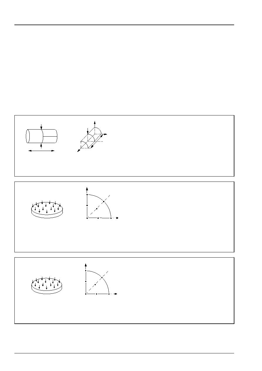
Code_Aster
®
Version
6.3
Titrate:
Note of use of the elements plates and hulls
Date:
21/06/02
Author (S):
A. ASSIRE, P. MASSIN, F. LEBOUVIER
Key
:
U2.02.01-A
Page
:
30/50
Instruction manual
U2.02 booklet: Elements of structure
HT-66/02/003/A
2.5 Examples
The case-tests selected here are conventional case-tests resulting from the literature and which are usually
used to validate this type of elements.
It is reminded the meeting that modelings DKT correspond to the theory of Coils-Kirchhoff and them
DST modelings, Q4G with the theory with transverse energy of shearing (Reissner). Results
for modeling COQUE_3D are presented only for one theory with energy of shearing
transverse.
2.5.1 Analyze static linear
SSLS20
C
B
With
D
L
y
X
Z
R
F
eighth of cylinder
C
D
F
B
L
F
With
Length
L = 10.35 m
Radius
R = 4.953 m
Thickness
T = 0.094 m
Titrate:: Cylindrical hull pinch on free board
Documentation V: [V3.03.020]
Modelings:
SSLS20A DKT
SSLS20B COQUE_3D
MEC3QU9H
SSLS20C COQUE_3D
MEC3TR7H
SSLS100
With
B
C
O
D
E
F
y
X
1/4 of plate
Radius
R = 1 m
Thickness
T = 0.1 m
Titrate: Plate circular embedded subjected to a pressure
uniform.
Documentation V: [V3.03.100]
Modelings:
SSLS100K
COQUE_3D
MEC3QU9H
SSLS100L
COQUE_3D
MEC3TR7H
SSLS100B DKT
SSLS100E DKQ
SSLS100F DST
SSLS100G DSQ
SSLS100H Q4G
SSLS100I, J
COQU_AXIS
SSLS101
With
B
C
O
D
E
F
y
X
1/4 of plate
Radius
R = 1 m
Thickness
T = 0.1 m
Titrate: Plate circular posed subjected to a pressure
uniform.
Documentation V: [V3.03.101]
Modelings:
SSLS101J
COQUE_3D
MEC3QU9H
SSLS101I
COQUE_3D
MEC3TR7H
SSLS101B DKT
SSLS101E DKQ
SSLS101F DST
SSLS101G DSQ
SSLS101H Q4G
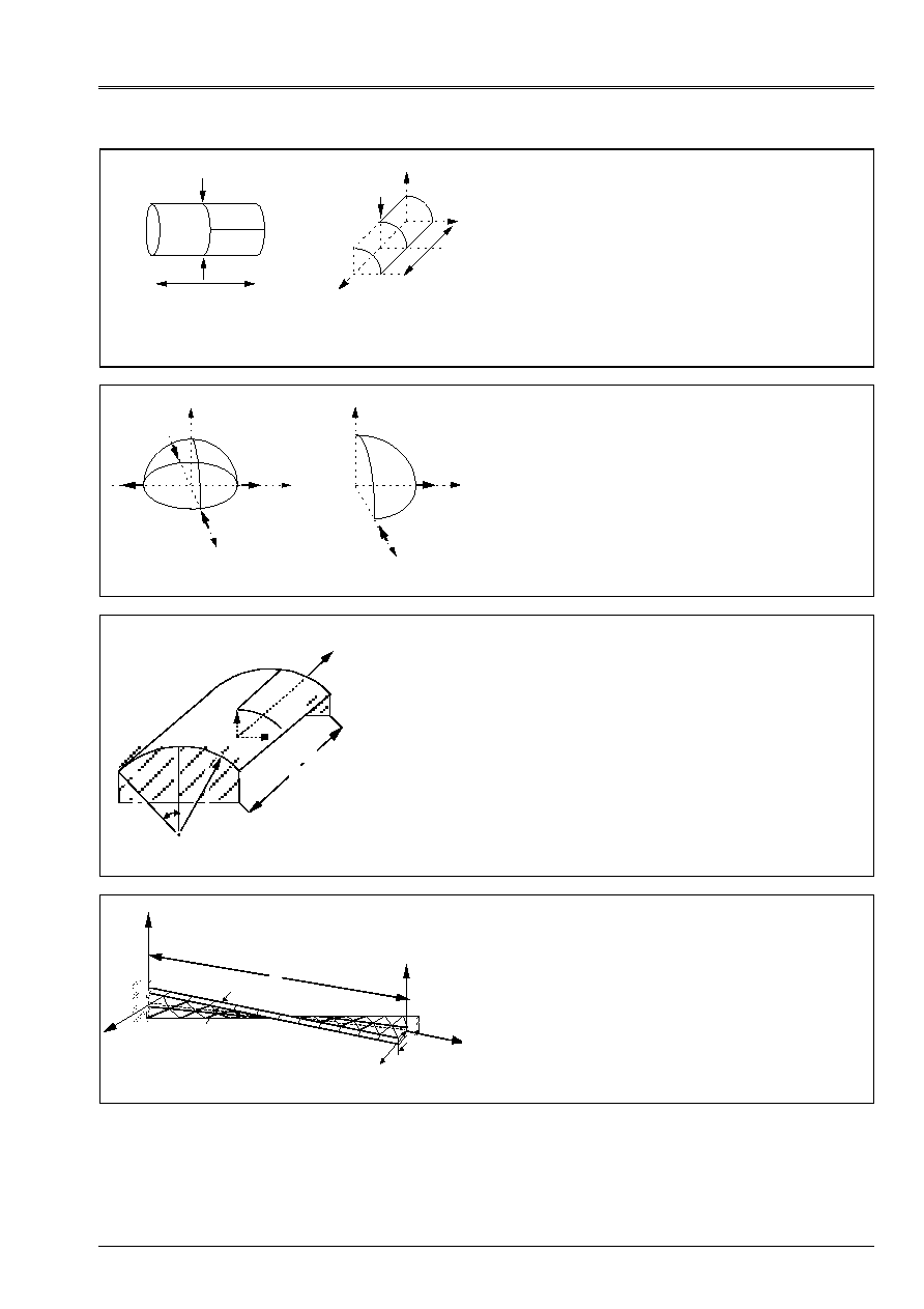
Code_Aster
®
Version
6.3
Titrate:
Note of use of the elements plates and hulls
Date:
21/06/02
Author (S):
A. ASSIRE, P. MASSIN, F. LEBOUVIER
Key
:
U2.02.01-A
Page
:
31/50
Instruction manual
U2.02 booklet: Elements of structure
HT-66/02/003/A
SSLS104
With
D
C
B
L
y
X
Z
R
F
eighth of cylinder
With
B
F
C
D
L
F
Length
L = 600
Radius
R = 300
Thickness
T = 3
Titrate: Cylindrical hull pinch with diaphragm.
Documentation V: [V3.03.104]
Modelings:
SSLS104B COQUE_3D MEC3QU9H
SSLS104C COQUE_3D MEC3TR7H
SSLS104A DKT
SSLS105
C
With
B
2KN
2KN
Z
X
y
C
With
B
Z
y
X
Radius
R = 10. m
Thickness
T = 0.04 m
Titrate: Doubly gripped hemisphere.
Documentation V: [V3.03.105]
Modelings:
SSLS105B COQUE_3D MEC3QU9H
SSLS105? COQUE_3D MEC3TR7H
SSLS105A DKT
SSLS107
Free
With
D
y
X
Z
R
Length
Radius
Thickness
Angular section
L = 6. m
R = 3. m
T = 0.03 m
= 40°
C
L
B
Titrate: Cylindrical panel subjected to its own weight.
Documentation V: [V3.03.107]
Modelings:
SSLS107A
COQUE_3D
MEC3QU9H
SSLS107B
COQUE_3D
MEC3TR7H
SSLS108
With
F
Y
F
Z
B
X
B
C
O
Y
Z
H
L
Titrate: Helicoid hull under concentrated loadings.
Documentation V: [V3.03.108]
Modelings:
SSLS108A
COQUE_3D
MEC3QU9H
SSLS108B
COQUE_3D
MEC3TR7H
Note:
Disadvised use with DKT/DKQ, without
transverse shearings.

Code_Aster
®
Version
6.3
Titrate:
Note of use of the elements plates and hulls
Date:
21/06/02
Author (S):
A. ASSIRE, P. MASSIN, F. LEBOUVIER
Key
:
U2.02.01-A
Page
:
32/50
Instruction manual
U2.02 booklet: Elements of structure
HT-66/02/003/A
Other case-tests are more briefly described in the following table:
Name Modeling
Remarks
hpla100a
hpla100b
hpla100c
hpla100d
hpla100e
hpla100f
2d_AXIS
COQUE_AXIS
COQUE_3D
COQUE_3D
HULL
HULL
Titrate: Heavy thermoelastic hollow roll in uniform rotation.
Documentation V: [V7.01.100]
The purpose of this test is to test the second corresponding members
with the effects of gravity and an acceleration due to a rotation
uniform.
The analytical solutions for the COQUE_3D include the variation of
metric in the thickness of the hull. Analytical solutions for
the plates are without correction of metric
hsls01a
hsls01b
DKT/DST/Q4G
COQUE_3D
Titrate: Embedded thin section subjected to a heat gradient in
the thickness.
Documentation V: [V7.11.001]
hsns100a
hsns100b
COQUE_3D/DKT
COQUE_3D/DKT
Titrate: Plate subjected to a variation in temperature in
the thickness.
Documentation V: [V7.23.100]
This case-test makes it possible to test two ways of imposing the field
thermics. The results obtained has some and B must be identical,
but the reference solutions obtained are numerical.
ssll102a
COQUE_C_PLAN
Titrate: Fixed beam subjected to unit efforts
Documentation V: [V3.01.102]
ssls501a
COQUE_D_PLAN
Titrate: Roll infinitely long subjected to two lines of loads.
Documentation V: [V3.03.501]
ssls114a
ssls114b
ssls114c
ssls114d
ssls114i
ssls114j
ssls114k
COQUE_3D
COQUE_3D
DKT/DST
DKQ/DSQ
COQUE_AXI
COQUE_C_PLAN
COQUE_D_PLAN
Titrate: Setting under pressure of a cylindrical quarter of binding ring.
Documentation V: [V3.03.114]
Analytical reference solution. Allows to test the term of
pressure and orientation of the normals. One tests the results in
radial displacement and in radial stresses.

Code_Aster
®
Version
6.3
Titrate:
Note of use of the elements plates and hulls
Date:
21/06/02
Author (S):
A. ASSIRE, P. MASSIN, F. LEBOUVIER
Key
:
U2.02.01-A
Page
:
33/50
Instruction manual
U2.02 booklet: Elements of structure
HT-66/02/003/A
2.5.2 Modal analysis in dynamics
Name Modeling
Remarks
sdls01a
sdls01b
sdls01c
sdls01d
sdls01e
sdls01f
sdls01g
sdls01h
DKT
DKT
DKT
DKT
COQUE_3D
COQUE_3D
COQUE_3D
COQUE_3D
Titrate: Thin square plate free or embedded on an edge
Documentation V: [V2.03.001]
It is of a modal calculation and a harmonic calculation of answer. For
modal calculation, it acts to calculate the clean modes of bending
of a thin square plate free or embedded on an edge.
has - Edges of the plate directed according to axes' of the reference mark.
B - Unspecified orientation of the plate and harmonic answer for
the embedded plate.
C - Modal calculation by conventional dynamic under-structuring and
cyclic.
D - Modal calculation following a under-structuring of Guyan.
E - Edges of the plate directed according to axes' of the reference mark.
F - Edges of the plate directed according to axes' of the reference mark.
G - Unspecified orientation of the plate and harmonic answer for
the embedded plate.
H - Unspecified orientation of the plate and harmonic answer for
the embedded plate.
·
For A and B the precision on the Eigen frequencies is lower
to 1% until the sixth mode of bending
·
For C in under-structuring, the quality of the results can be
improved by the use of a finer mesh of substructure.
·
For D, it is necessary in order to obtain an accuracy of 1% on
Eigen frequencies to also condense on the nodes medium
edges.
·
For E, F, G and H, the precision on the Eigen frequencies is
lower than 1% until the sixth mode of bending for
elements quadrangle and lower than 2% for the elements
triangle.
The element of hull MEC3QU9H powerful is compared with the element
DKT which is itself more powerful than element MEC3TR7H.
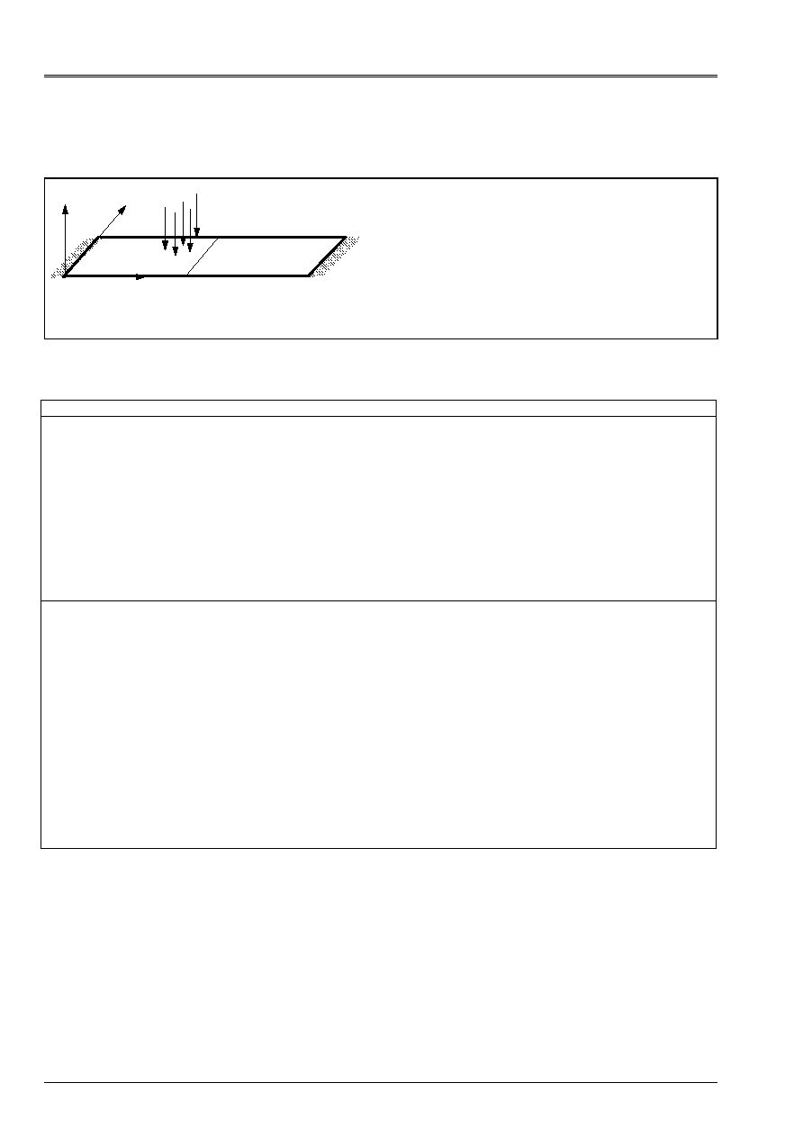
Code_Aster
®
Version
6.3
Titrate:
Note of use of the elements plates and hulls
Date:
21/06/02
Author (S):
A. ASSIRE, P. MASSIN, F. LEBOUVIER
Key
:
U2.02.01-A
Page
:
34/50
Instruction manual
U2.02 booklet: Elements of structure
HT-66/02/003/A
2.5.3 Analyze static nonlinear material
SSNL501
Z
y
X
Titrate: Fixed beam subjected to a uniform pressure.
Documentation V: [V6.02.501]
Modelings:
SSNL501E COQUE_3D MEC3QU9H
SSNL501D COQUE_3D MEC3TR7H
SSNL501B DKT
SSNL501C DKQ
SSNL501A COQUE_C_PLAN
Other case-tests are more briefly described in the following table:
Name Modeling
Remarks
ssnp15a
ssnp15b
ssnp15c
ssnp15d
3D
C_PLAN
DKT
COQUE_3D
Titrate: Square plate in traction-shearing - Von Mises
(isotropic work hardening).
Documentation V: [V6.03.015]
A plate, made up of a plastic material with work hardening
isotropic linear, is subjected to a tensile load and an effort of
shearing. Even if the test validates the law of behavior rather that
the elements to which it applies, it makes it possible to test them
values of the stresses, the efforts and the deformations in
reference mark defined by user (ANGL_REP).
ssnv115a
ssnv115b
ssnv115c
ssnv115d
ssnv115e
ssnv115f
D_PLAN
DKT
DKT
COQUE_3D
COQUE_3D
COQUE_D_PLAN
Titrate: Iron corrugated in nonlinear behavior.
Documentation V: [V6.04.115]
This test validates the nonlinear behaviors in
modelings of plates or thin hulls. Modeling A
(2D D_PLAN) is used as reference. The values of displacements are
tested.
Modeling COQUE_D_PLAN reveals variations on
side displacements of sheet of about 13% compared to
other modelings. This is due to the method of integration in
the thickness which utilizes only 5 points of Gauss for this
modeling, compared with 19 points for elements DKT and DKQ and
8 points for modeling D_PLAN.
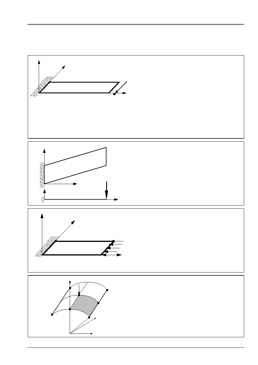
Code_Aster
®
Version
6.3
Titrate:
Note of use of the elements plates and hulls
Date:
21/06/02
Author (S):
A. ASSIRE, P. MASSIN, F. LEBOUVIER
Key
:
U2.02.01-A
Page
:
35/50
Instruction manual
U2.02 booklet: Elements of structure
HT-66/02/003/A
2.5.4 Analyze static nonlinear geometrical
SSNV138
M
X
y
X
Titrate: Plate cantilever in great rotations subjected to
one moment.
Documentation V: [V6.04.138]
Modelings:
SSNV138 COQUE_3D
MEC3QU9H
SSNV138 COQUE_3D
MEC3TR7H
Note:
Greatest rotation reached is slightly lower than
. The results obtained are very satisfactory, the variation
maximum is lower than 0.01%. It is necessary
to increase the value of COEF_RIGI_DRZ (10th-5 by
defect) with 0.001 in order to be able to increase the value of
the swing angle which one can reach.
SSNV139
X
y
X
Z
P
Titrate: Plate skews.
Documentation V: [V6.04.139]
Modelings:
SSNV139 COQUE_3D
MEC3QU9H
SSNV139 COQUE_3D
MEC3TR7H
SSNL502
P
X
y
Z
Titrate: Beam in buckling.
Documentation V: [V6.02.502]
Modelings:
SSNL502 COQUE_3D
MEC3QU9H
SSNL502 COQUE_3D
MEC3TR7H
SSNS501
y
Z
X
Titrate: Great displacements of a cylindrical panel.
Documentation V: [V6.05.501]
Modelings:
SSNS501 COQUE_3D
MEC3QU9H
SSNS501 COQUE_3D
MEC3TR7H

Code_Aster
®
Version
6.3
Titrate:
Note of use of the elements plates and hulls
Date:
21/06/02
Author (S):
A. ASSIRE, P. MASSIN, F. LEBOUVIER
Key
:
U2.02.01-A
Page
:
36/50
Instruction manual
U2.02 booklet: Elements of structure
HT-66/02/003/A
Other case-tests are more briefly described in the following table:
Name Modeling
Remarks
ssnv140a
ssnv140b
COQUE_3D
COQUE_3D
Titrate: Embedded cylindrical panel subjected to a surface force.
Documentation V: [V6.04.140]
This force is constant for modeling has and following in
modeling B. The goal of this case-test is to check modeling
COQUE_3D non-linear geometrical by using the algorithm of setting with
day of large rotations 3D GREEN_GR of STAT_NON_LINE and of
to check the processing of the following pressures. Data of it
problem correspond to a thin hull H/L=0.625% what is
severe for the finite element triangle MECQTR7H (case of blocking with
transverse shearing).
ssnv141a
COQUE_3D
Titrate: Segment of a sphere pinch.
Documentation V: [V6.04.141]
The data of this problem correspond to a thin hull
H/L=0.4% what is severe for the finite element triangle MECQTR7H (case of
blocking with transverse shearing). It is necessary to increase
value of the COEF_RIGI_DRZ which allots a rigidity around the normal
elements of hull which is worth by defect 10
- 5
the smallest rigidity of
bending around the directions in the plan of the be able hull in order to
to increase the value of the swing angle which one can reach.
values of this coefficient up to 10
- 3
remain licit.
ssnv144a
COQUE_3D
Titrate: Bend in cross-bending, elastic, embedded on dimensioned and subjected
with a linear force equivalent to one bending moment.
Documentation V: [V6.04.144]
The goal of this case-test is to check that, for the elements COQUE_3D,
quasi-static solutions into linear geometrical (VMIS_ISOT_LINE
in STAT_NON_LINE) and into nonlinear geometrical (GREEN_GR in
STAT_NON_LINE) are close to the linear static solution
(MECA_STATIQUE) in the field of the small disturbances.
ssnv145a
ssnv145b
COQUE_3D
COQUE_3D
Titrate: Plate cantilever in great rotations subjected has a pressure
following.
Documentation V: [V6.04.145]
The goal of this case-test is to check modeling COQUE_3D (mesh
TRIA7, QUAD9) in the presence of pressure of a following type.
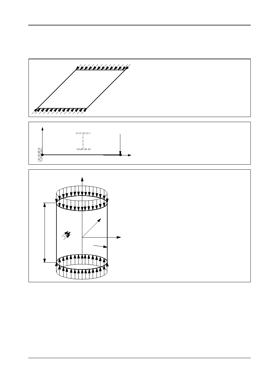
Code_Aster
®
Version
6.3
Titrate:
Note of use of the elements plates and hulls
Date:
21/06/02
Author (S):
A. ASSIRE, P. MASSIN, F. LEBOUVIER
Key
:
U2.02.01-A
Page
:
37/50
Instruction manual
U2.02 booklet: Elements of structure
HT-66/02/003/A
2.5.5 Analyze in buckling of Euler
SSLS110
Titrate: Stability of a compressed square plate.
Documentation V: [V3.03.110]
Modelings:
SSLS110 COQUE_3D
MEC3QU9H
SSLS110 COQUE_3D
MEC3TR7H
SDLS504
X, U
y, v
Z, W
P
Titrate: Side buckling of a beam (discharge).
Documentation V: [V2.03.504]
Modelings:
SDLS504 COQUE_3D
MEC3QU9H
SDLS504 COQUE_3D
MEC3TR7H
SDLS505
L
R
Z, W
y, v
X, U
p
NR
Titrate: Buckling of a cylindrical envelope under
external pressure.
Documentation V: [V2.03.505]
Modelings:
SDLS505 COQUE_3D
MEC3QU9H
SDLS505 COQUE_3D
MEC3TR7H
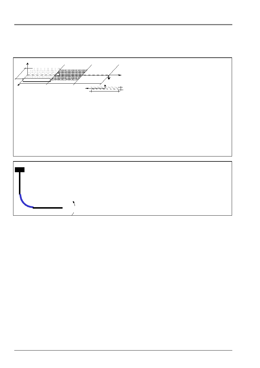
Code_Aster
®
Version
6.3
Titrate:
Note of use of the elements plates and hulls
Date:
21/06/02
Author (S):
A. ASSIRE, P. MASSIN, F. LEBOUVIER
Key
:
U2.02.01-A
Page
:
38/50
Instruction manual
U2.02 booklet: Elements of structure
HT-66/02/003/A
2.5.6 Connections hulls and other machine elements
SSLX100
Z
y
X
O
D
C
C1
C2
M2
M4
M1
NR
L1
L2
L3
hull thickness 1
beam of section
rectangular
With
B
M
F = - 1.
Z
y
has
B
beam of section
rectangular
has
L1 = L2 = L3 = 10 mm
B = 1 mm
= 3 mm have
Titrate: Mix 3D-Hull-Beam in bending.
Documentation V: [V3.05.100]
Modelings:
SSLX100A
3D
1
MECA_HEXA20
DKT
4
MEDKTR3
POU_D_E 2
POU_D_E
SSLX100B
3D
1
MECA_HEXA20
DKT
4
MEDKTR3
POU_D_E 2
POU_D_E
SSLX100C
3D
1
MECA_HEXA20
DKT
4
MEDKTR3
COQUE_C_PLAN
1
MECPSE3
The axial arrows, stresses, deformations are tested
and bending moments in 4 points of the axis of
beam.
SSLX102
With
B
C
D
Mz
Titrate: Piping bent in bending.
Documentation V: [V3.05.102]
Modelings:
SSLX102A
DKT and PIPE
(connection COQUE_TUYAU)
SSLX102D
HULL and BEAM
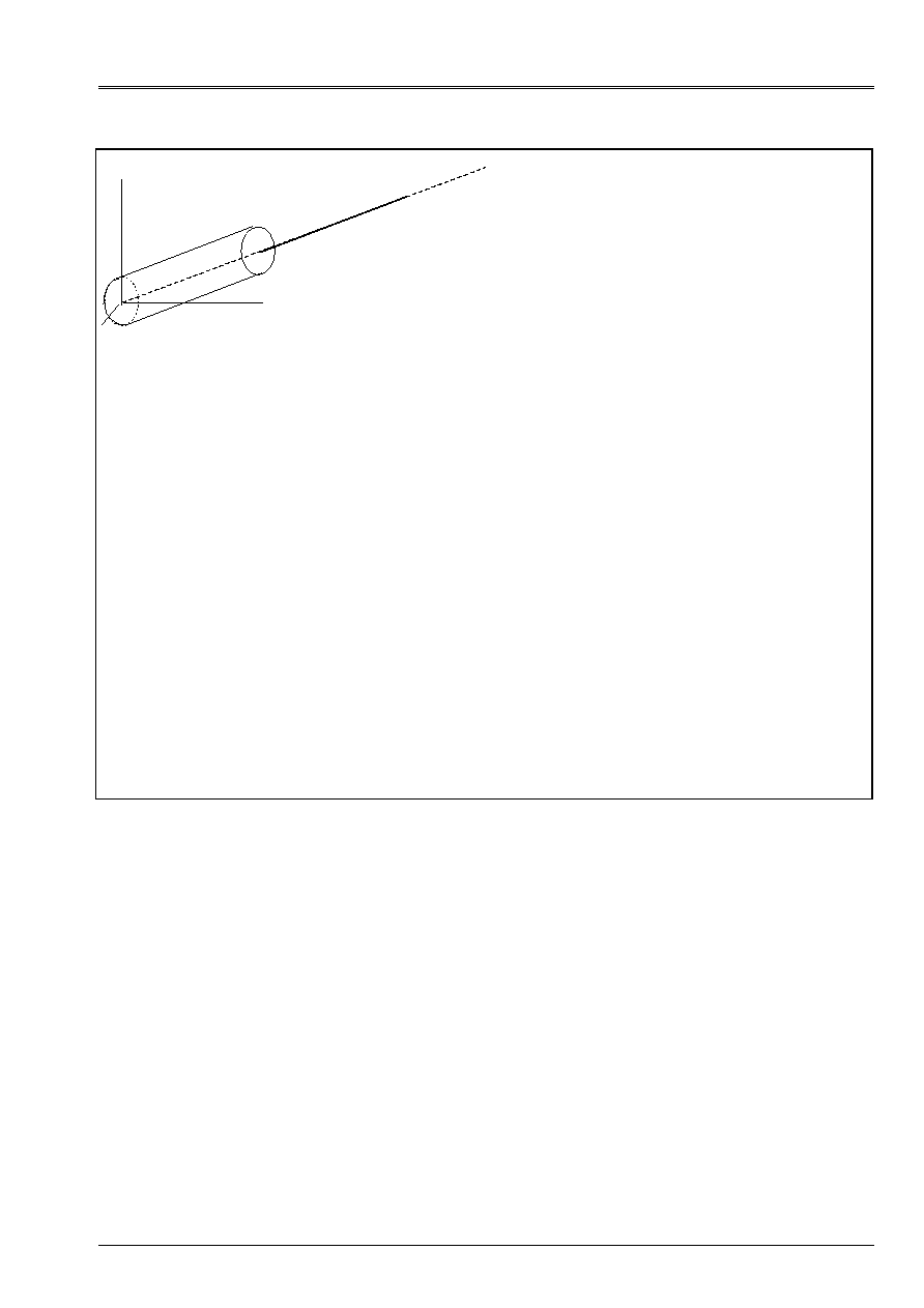
Code_Aster
®
Version
6.3
Titrate:
Note of use of the elements plates and hulls
Date:
21/06/02
Author (S):
A. ASSIRE, P. MASSIN, F. LEBOUVIER
Key
:
U2.02.01-A
Page
:
39/50
Instruction manual
U2.02 booklet: Elements of structure
HT-66/02/003/A
SSLX101A
P1
P2
x1
X
y
Z
Titrate: Pipe right modelized in hulls and beams
[V3.05.101].
Documentation V: [V3.05.101]
Modelings:
SSLX101A
DIS_TR
POI1
DKT
MEDKQU4
POU_D_E 2
SEG2
Embedding of the hull on the P1 edge. Bending and
traction in x1. Variation from 3 to 5% on displacements
and rotations in P2 with the analytical solution, due to
mesh hull with plane elements.
SSLX101B
DKT
MEDKQU4,
METUSEG3
PIPE
METUSEG3,
MEDKQU4
DIS_TR
POI1
This modeling aims to test the connection
hull pipe in the presence of unit loadings:
traction, bending and of torsion. The reference solution
is analytical (RDM). The variation with the solution
numerical is explained by the fact that the mesh in
hulls actually consists of plane elements
(breakages). The geometry of the pipe is thus itself
approached.
SSLX102A DKT
MEDKQU4,
METUSEG3
PIPE
MEDKQU4,
METUSEG3
Modeling A utilizes the connection
coque_tuyau, the solution obtained (2.7% of variation in
cross-bending, and 0.4% in bending except plan, by report/ratio
with the reference: mesh any hulls (modeling D)
allows to test the correct operation of
connection coque_tuyau.

Code_Aster
®
Version
6.3
Titrate:
Note of use of the elements plates and hulls
Date:
21/06/02
Author (S):
A. ASSIRE, P. MASSIN, F. LEBOUVIER
Key
:
U2.02.01-A
Page
:
40/50
Instruction manual
U2.02 booklet: Elements of structure
HT-66/02/003/A
3 Thermics
For the resolution of chained thermomechanical problems, one must use for thermal calculation
finite elements of thermal hull [R3.11.01]. These elements are elements plates, or
linear in the case of structures of revolution or invariant structures along an axis.
curvature of the structure is not taken into account in itself. The metric one of the tangent plan of
each element is calculated by supposing that all the nodes are coplanar. These elements
suppose a distribution a priori parabolic of temperature in the thickness, which results from one
asymptotic development in linear thermics for a low thickness of hull, when them
variations in temperatures are not too important. It is it should be noted that a model based on one
development of the richer field of temperature in the thickness sees its terms of a higher nature
to two to converge towards zero when the hull is thin. One cannot thus deal with the problems of
thermal shocks with strong variation of the profile of temperature in the thickness with these hulls.
methods of use of these elements are presented in [U1.22.01].
3.1
Definition of the problem
3.1.1 Space discretization and assignment of a modeling
: operator
AFFE_MODELE
3.1.1.1 Degrees of freedom
The degrees of freedom are the temperatures TEMP (temperature on the average surface of the hull),
TEMP_INF (temperature on the lower surface of the hull), and TEMP_SUP (temperature on
upper surface of the hull).
3.1.1.2 Meshs support of the matrices of rigidity
Modeling
Net
Nature of the mesh
Finite element Remarks
HULL QUAD9
QUAD8
QUAD4
TRIA7
TRIA6
TRIA3
plane
plane
plane
plane
plane
plane
THCOQU9
THCOQU8
THCOQU4
THCOTR7
THCOTR6
THCOTR3
nodes with 3 co-ordinates X, y, Z
Not supposed COQUE_PLAN SEG3 planes THCPSE3
nodes with 2 co-ordinates X, y
Not supposed COQUE_AXIS SEG3 planes THCASE3
nodes with 2 co-ordinates X, y
For THCOTRi, only the 3 nodes are exploited to define the local geometry (tangent plan,
normal). For THCOQUi, one considers that the element is plane and its tangent plan is defined by
defect by 3 of the 4 nodes of the element.

Code_Aster
®
Version
6.3
Titrate:
Note of use of the elements plates and hulls
Date:
21/06/02
Author (S):
A. ASSIRE, P. MASSIN, F. LEBOUVIER
Key
:
U2.02.01-A
Page
:
41/50
Instruction manual
U2.02 booklet: Elements of structure
HT-66/02/003/A
3.1.1.3 Meshs support of the loadings
Modeling Nets
Element
finished Remarks
HULL SEG2
THCOSE2
with TRIA3 and QUAD4
HULL SEG3
THCOSE3
with TRIA6,7 and QUAD8, 9
All the loadings applicable to the breakages of the elements of hull are treated by discretization
direct on the mesh support of the element in temperature formulation. No mesh of loading
is not thus necessary for the faces of the elements of hulls.
For the applicable loadings on the edges of the elements of hull, a mesh support of the type
SEG2 (element THCOSE2) or SEG3 (element THCOSE3) must be used.
For the imposed temperatures the meshs support are meshs reduced to a point.
3.1.1.4 Model
:
AFFE_MODELE
The assignment of modeling passes through operator AFFE_MODELE [U4.41.01].
AFFE_MODELE
Remarks
AFFE
PHENOMENON:
“THERMAL”
MODELING “COQUE_3D”
“COQUE_C_PLAN”
“COQUE_D_PLAN”
“COQUE_AXIS”
3.1.2 Elementary characteristics: AFFE_CARA_ELEM
In this part, operands characteristic of the elements of plates and hulls in thermics
are described. The documentation of use of operator AFFE_CARA_ELEM is [U4.42.01].
AFFE_CARA_ELEM HULL
COQUE_PLAN
COQUE_AXIS
Remarks
HULL
THICK
· ·
·
The characteristics assigned to materials are the same ones as for a mechanical calculation. It is with
to note that it is not useful to define a particular reference mark for the analysis of the results of calculation
thermics because those are limited to the fields of temperature, scalar size, independent of
reference frame used.
3.1.3 Materials
:
DEFI_MATERIAU
DEFI_MATERIAU HULL
COQUE_PLAN
COQUE_AXIS
Remarks
THER
· ·
·
THER_FO
· ·
·
The materials used with elements plates or hulls in thermics can have
linear characteristics thermal constant or dependant on the increment of loading.

Code_Aster
®
Version
6.3
Titrate:
Note of use of the elements plates and hulls
Date:
21/06/02
Author (S):
A. ASSIRE, P. MASSIN, F. LEBOUVIER
Key
:
U2.02.01-A
Page
:
42/50
Instruction manual
U2.02 booklet: Elements of structure
HT-66/02/003/A
3.1.4 Limiting loadings and conditions: AFFE_CHAR_THER and AFFE_CHAR_THER_F
The assignment of the loadings and the boundary conditions on a thermque model is carried out with aid
operators AFFE_CHAR_THER, if loadings and boundary conditions mechanical on one
system are actual values depending on no parameter, or AFFE_CHAR_THER_F, if
these values are functions of the position or the increment of loading.
The documentation of use of AFFE_CHAR_THER and AFFE_CHAR_THER_F is [U4.44.02].
3.1.4.1 List key words factor of AFFE_CHAR_THER
The affected values of the loadings are real and do not depend on any parameter.
AFFE_CHAR_THER
Generals
HULL COQUE_PLAN
COQUE_AXIS Remarks
TEMP_IMPO · · ·
AFFE_CHAR_THER
private individuals
HULL COQUE_PLAN
COQUE_AXIS Remarks
FLUX_REP
·
· ·
on the faces and the edges
surface elements
EXCHANGE ·
·
·
on the faces and the edges
surface elements
·
TEMP_IMPO: Key word factor usable to impose, on nodes or groups of
nodes, a temperature.
·
FLUX_REP: Key word factor usable to apply normal flows to a face of hull
thermics defined by one or more meshs or of the groups of meshs of the triangle type or
quadrangle.
·
EXCHANGE: Key word factor usable to apply conditions of exchange with one
outside air temperature with a face of hull, defined by one or more meshs or groups
meshs of the triangle type or quadrangle.
3.1.4.2 List key words factor of AFFE_CHAR_THER_F
The affected values of the loadings can be a function of the total co-ordinates and time,
or of the temperature in nonlinear thermics (except in hulls).
AFFE_CHAR_THER_F
Generals
HULL COQUE_PLAN COQUE_AXIS Remarks
TEMP_IMPO
· ·
·
AFFE_CHAR_THER_F
private individuals
HULL COQUE_PLAN COQUE_AXIS Remarks
FLUX_REP
·
·
·
on the faces and the edges of
surface elements
EXCHANGE
·
·
·
on the faces and the edges of
surface elements

Code_Aster
®
Version
6.3
Titrate:
Note of use of the elements plates and hulls
Date:
21/06/02
Author (S):
A. ASSIRE, P. MASSIN, F. LEBOUVIER
Key
:
U2.02.01-A
Page
:
43/50
Instruction manual
U2.02 booklet: Elements of structure
HT-66/02/003/A
3.2 Resolution
3.2.1 Transitory calculations: operator THER_LINEAIRE
Option of calculation
transient
HULL COQUE_PLAN
COQUE_AXIS
Remarks
CHAR_THER_EVOL
·
It is here about the processing of the problems of thermics evolutionary.
3.3
Additional calculations and postprocessings
3.3.1 Calculations in postprocessing
One presents hereafter the options of postprocessing for the elements of plates and hulls
OPTIONS
elementary
HULL COQUE_PLAN COQUE_AXIS Remarks
“FLUX_ELNO_TEMP”
·
“FLUX_ELGA_TEMP”
·
“NIVE_COUCHE”
·
·
FLUX_ELNO_TEMP: This option carries out the calculation of heat transfer rate to the nodes from
the temperature.
·
FLUX_ELGA_TEMP: This option carries out the calculation of heat transfer rate at the points of integration
starting from the temperature.
·
NIVE_COUCHE: Option which specifies for layer N the ordinate where one wishes to have the field
of temperature. A calculation in internal skin is indicated by “INF”, in external skin by
“SUP” and on the average layer by “MOY”.

Code_Aster
®
Version
6.3
Titrate:
Note of use of the elements plates and hulls
Date:
21/06/02
Author (S):
A. ASSIRE, P. MASSIN, F. LEBOUVIER
Key
:
U2.02.01-A
Page
:
44/50
Instruction manual
U2.02 booklet: Elements of structure
HT-66/02/003/A
3.4 Examples
One gives here the list of the case-tests available for the thermal hulls. They are case-tests of
stationary thermics. The results are correct for the whole of these case-tests, whatever
the element used.
Name
Modeling
Element
Remarks
tplp301a
HULL
THCOTR3
Titrate: Plate with imposed temperature
distributed sinusoïdalement on a side.
Documentation: [V4.05.301]
tplp302a HULL
THCOTR6
Titrate: Rectangular plate with temperature
imposed on the sides.
Documentation: [V4.05.302]
tpls100a
tpls100b
HULL
COQUE_PLAN
THCOTR6/THCOTR3
THCPSE3
Titrate: Infinite plate subjected to a couple of flow
of heat antisymmetric stationary on its
two half-faces.
Documentation: [V4.03.100]
Conduction is linear, homogeneous and isotropic.
tpls101a
tpls101b
tpls101c
tpls101d
tpls101e
HULL THCOTR6/THCOSE3
THCOQU4/THCOSE2
THCOQU8/THCOSE3
THCOQU9/THCOSE3
THCOTR7/THCOSE3
Titrate: Infinite plate subjected to a couple of
thermal conditions with outside,
symmetrical compared to the average layer.
Documentation: [V4.03.101]
Conduction is linear, homogeneous and isotropic.
tpls302a
tpls302b
tpls302c
tpls302d
HULL THCOQU8/THCOSE3
THCOQU4/THCOSE2
THCOQU9/THCOSE3
THCOTR7/THCOSE3
Titrate: Rectangular plate with convection and
imposed temperature
Documentation: [V4.03.302]

Code_Aster
®
Version
6.3
Titrate:
Note of use of the elements plates and hulls
Date:
21/06/02
Author (S):
A. ASSIRE, P. MASSIN, F. LEBOUVIER
Key
:
U2.02.01-A
Page
:
45/50
Instruction manual
U2.02 booklet: Elements of structure
HT-66/02/003/A
4 Chaining
thermomechanics
4.1 Formalism
For the resolution of chained thermomechanical problems, one must use for thermal calculation
finite elements of thermal hull [R3.11.01] whose field of temperature is recovered like
input datum of the Code _Aster for mechanical calculation. It is necessary thus that there is compatibility between
thermal field given by the thermal hulls and that recovered by the mechanical hulls. It
the last is defined by the knowledge of 3 fields TEMP_SUP, TEMP and TEMP_INF given in skins
lower, medium and higher of hull. The table below indicates these compatibilities:
Modeling
THERMICS
Maille Elément Nets Element Modeling
MECHANICS
HULL QUAD9
THCOQU9
QUAD9
MEC3QU9H
COQUE_3D
HULL QUAD8
THCOQU8
HULL QUAD4
THCOQU4
QUAD4
MEDKQU4
MEDSQU4
MEQ4QU4
DKT
DST
Q4G
HULL TRIA7
THCOTR7
TRIA7
MEC3TR7H
COQUE_3D
HULL TRIA6
THCOTR6
HULL TRIA3
THCOTR3
TRIA3
MEDKTR3
MEDSTR3
DKT
DST
COQUE_PLAN SEG3 THCPSE3
SEG3
SEG3
METDSE3
METCSE3
COQUE_D_PLAN
COQUE_C_PLAN
COQUE_AXIS SEG3 THCASE3
SEG3 MECXSE3
COQUE_AXIS
Note:
·
Nodes of the thermal elements of hulls and plates or hulls
mechanics must correspond. Mesh for thermics and mechanics
the same number and the same type of meshs will thus have.
·
The elements of thermal hulls surface are treated like plane elements
by projection of the initial geometry on the level defined by the first 3 nodes. For
the chaining of calculations with mechanical curved elements it is thus necessary
that the geometry of the plate is not too distant from that of the hull. When
structure is curved, that thus requires for thermal calculation to net it way
sufficient fine in order to have correct results in preparation for the part
mechanics. Only the linear elements of thermics are associated perfectly
corresponding linear elements in mechanics fascinating bus of account curvature of
the structure with a grid.
·
The chaining with multi-layer materials is not available for the moment.
·
The thermomechanical chaining is also possible if one knows, analytically or by
experimental measurements, variation of the field of temperature in the thickness of
the structure or certain parts of the structure. In this case one works with one
card of temperature defined a priori; the field of temperature is not given any more by
three values TEMP_INF, TEMP and TEMP_SUP of thermal calculation obtained by
EVOL_THER. Operator DEFI_NAPPE allows to create such profiles of temperatures with
to leave the data provided by the user. These profiles are affected by the control
CREA_CHAMPS and CREA_RESU (cf the case-test hsns100b). It will be noted that it is not
necessary for mechanical calculation that the number of points of integration in
the thickness is equal to the number of points of discretization of the field of temperature
in the thickness. The field of temperature is automatically interpolated at the points
of integration in the thickness of the elements of plates or hulls.
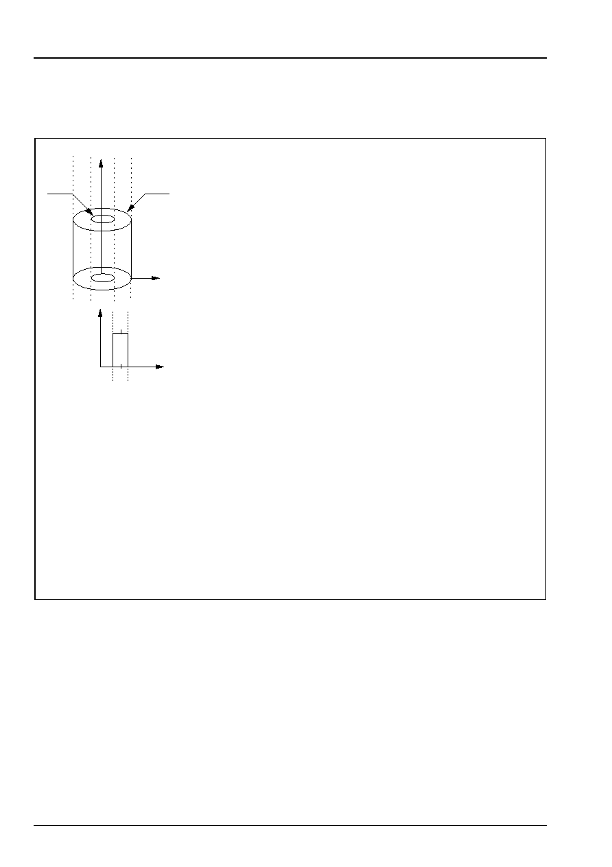
Code_Aster
®
Version
6.3
Titrate:
Note of use of the elements plates and hulls
Date:
21/06/02
Author (S):
A. ASSIRE, P. MASSIN, F. LEBOUVIER
Key
:
U2.02.01-A
Page
:
46/50
Instruction manual
U2.02 booklet: Elements of structure
HT-66/02/003/A
4.2 Examples
HPLA100
Z
R
R
E
R
I
F
B
D
With
C
R
Z
J
H
+
Interior radius
R
I
= 19.5 mm
External radius
R
E
= 20.5 mm
Not F
R = 20.0 mm
Thickness
H = 1.0 mm
Height
L = 10.0 mm
It is a question of studying a thermal phenomenon of dilation
where the fields of temperature are calculated with
THER_LINEAIRE by a stationary calculation:
- thermal dilation:
()
()
(
) (
) ()
H
R
R
T
T
T
T
T
T
I
S
I
S
ref.
/
.
2
5
.
0
-
+
+
+
=
-
with:
T
S
= 0.5 °C, T
I
= - 0.5 °C, T
ref.
= 0. °C
T
S
= 0.1 ° C, T
I
= 0.1 ° C, T
ref.
= 0. ° C
One tests the stresses, the efforts and moments
bending in L and Mr. the results of reference are
analytical. For modelings COQUE_3D one takes
in account variation of metric with the thickness of
hull. Very good results whatever the type
of element considered.
Titrate: Heavy thermoelastic hollow roll in
uniform rotation
Documentation: [V7.01.100]
Modelings:
HPLA100A
Thermics
PLAN 32
THPLQU8
Mechanics
AXIS 32
MEAXQU8
HPLA100B
Thermics
COQUE_PLAN
10 THCPSE3
Mechanics
COQUE_AXIS
10 MECXSE3
HPLA100C
Thermics
HULL
32
THCOQU9
Mechanics
COQUE_3D
32
MEC3QU9H
HPLA100D
Thermics
HULL
64
THCOTR7
Mechanics
COQUE_3D
64
MEC3TR7H
HPLA100E
Thermics
HULL
200
THCOQU4
Mechanics
HULL
200
MEDKQU4
HPLA100F
Thermics
HULL
400
THCOTR3
Mechanics
HULL
400
MEDKTR3
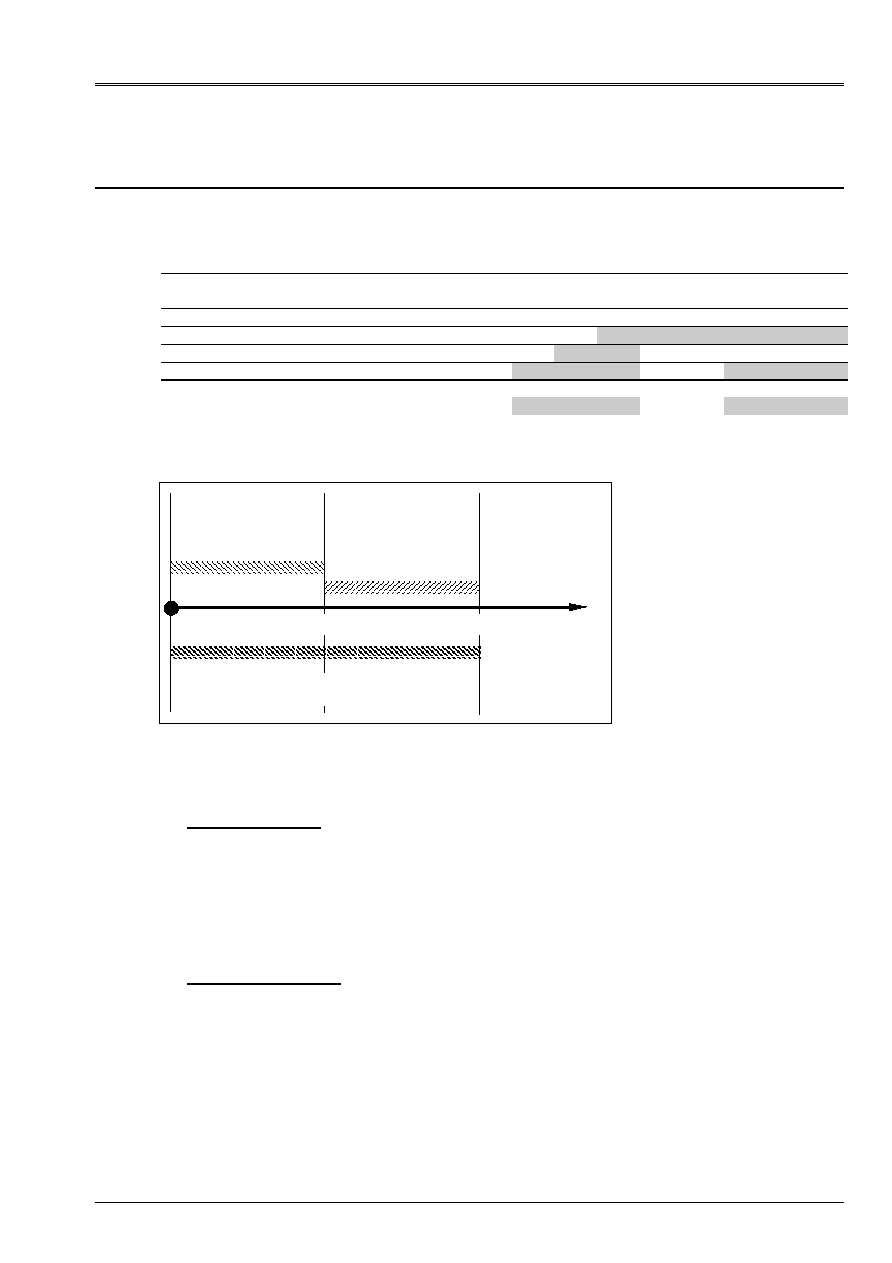
Code_Aster
®
Version
6.3
Titrate:
Note of use of the elements plates and hulls
Date:
21/06/02
Author (S):
A. ASSIRE, P. MASSIN, F. LEBOUVIER
Key
:
U2.02.01-A
Page
:
47/50
Instruction manual
U2.02 booklet: Elements of structure
HT-66/02/003/A
5
Conclusion and consultings of use
In the following table, a summary of the possibilities offered by modelings plates and
hulls is described.
Modeling -! DKT DST Q4G COQUE_3D COQUE_AXIS
Applicability
COQUE_D_PLAN
COQUE_C_PLAN
Linear statics: Isotropic material
X
X
X
X
X
Orthotropic, composite material
X X
Non-linear statics material
X
X
X
Geometrical non-linear statics
X
Analyze dynamic
X
X
X
X
X
Buckling of Euler
X
On the figure below the field of application of the plates and hulls is schematized.
H/L
0.1 (1/10)
0.05 (1/20)
DKT, DKQ
DST, DSQ, Q4G
COQUE_3D, COQUE_AXIS,
COQUE_C_PLAN, COQUE_D_PLAN
Plane elements
Curved elements
Thin hulls
Thick hulls
Appear 5-a: Fields of application of the plates and hulls
Some recommendations concerning the field of application of these elements:
·
Mean structures: for these structures, whose ratio H/L is lower than 1/20, effects of
transverse shearing can be neglected and the theory of Kirchhoff applies. One advises
to use for this type of structure of the elements plates DKT-DKQ or the elements of hull
curve (COQUE_3D, _AXIS, _C_PLAN, _D_PLAN. It is advised to use them preferably
elements DKT and DKQ which give very good results on displacements and more
approximate on the stresses (to be recommended for the vibratory analyzes). Even if one must
to use a great number of these elements, the execution times remain reasonable compared with
those of the curved elements.
·
Thick structures: for these structures, one will use elements of DST plate, DSQ and Q4G
who take account of transverse shearing with a factor of correction of shearing K =
5/6 (theory of Reissner) or preferably of the elements of curved hull. It makes it possible to pass
of a theory of Hencky-Mindlin-Naghdi for k=1, with a theory of Reissner for k=5/6. One
value of K = 5/6 is advised. By defect the coefficient of shearing is put at 5/6. This
preference rests on the fact that elements DST, DSQ and Q4G estimate them relatively badly
efforts compared to the curved elements of hull, like one could notice it on certain cases
tests of the paragraph [§2.5].

Code_Aster
®
Version
6.3
Titrate:
Note of use of the elements plates and hulls
Date:
21/06/02
Author (S):
A. ASSIRE, P. MASSIN, F. LEBOUVIER
Key
:
U2.02.01-A
Page
:
48/50
Instruction manual
U2.02 booklet: Elements of structure
HT-66/02/003/A
Elements DKT, DKQ, DST, DSQ and Q4G are plane elements, they do not take into account
curvature of the structures, it is thus necessary to refine the mesh if the curvature is
important if one wants to avoid the parasitic bendings.
Variation of metric of the geometry (i.e. its radius of curvature) according to sound
thickness is taken into account:
·
automatically for modeling COQUE_3D
·
defined by the user for modelings COQUE_AXIS, COQUE_D_PLAN and
COQUE_C_PLAN.
The optimal machine element in statics according to the whole of the case-tests of the paragraph
[§2.5] is the element of hull with 9 nodes MEC3QU9H, which makes it possible to obtain good displacements and
good stresses thanks to its P2 interpolation out of membrane. It is a general-purpose element which
can be at the same time used to represent very mean structures (H/L
1/100) or the thickest.
Like, in addition, the element of hull with 7 nodes MEC3TR7H is less powerful, it is
advised with the user to net his structure in hulls with the greatest possible number
quadrangles.
·
Non-linearity material: nonlinear behaviors (plasticity, etc) in plane stresses
are available for the elements of hull curves (COQUE_3D, COQUE_AXIS, COQUE_C_PLAN,
COQUE_D_PLAN) and the elements plates DKT-DKQ only. The plastic behavior
does not take the terms of transverse shearing which are treated in an elastic way, because it
transverse shearing is uncoupled from the plastic behavior. For a good representation
progression of plasticity through the thickness, one advises to use for integration
numerical 3 to 5 layers in the thickness for a number of points of being worth gauss
respectively 3, 5 and 11.
·
Geometrical non-linearity: nonlinear behaviors (great displacements large
rotations) in plane stresses are available for the elements of hull curves COQUE_3D
only.
·
Buckling of Euler: this type of analysis is available with the elements of curved hull
COQUE_3D only.
Elements corresponding to the machine elements exist in thermics; couplings
thermomechanical are thus available at the same time for the elements of plates and hulls. For
the moment these couplings are not possible for multi-layer materials.

Code_Aster
®
Version
6.3
Titrate:
Note of use of the elements plates and hulls
Date:
21/06/02
Author (S):
A. ASSIRE, P. MASSIN, F. LEBOUVIER
Key
:
U2.02.01-A
Page
:
49/50
Instruction manual
U2.02 booklet: Elements of structure
HT-66/02/003/A
6 Bibliography
[1]
J.L. Batoz, G. Dhatt “Modeling of the structures by finite elements: beams and plates”
Hermès, Paris (1990)
[2]
J.L. Batoz, G. Dhatt “Modeling of the structures by finite elements: hulls”
Hermès, Paris (1992)
[3]
D. Bui “Evolution of AFFE_CARA_ELEM” CR MN/97/004.
[4]
S. Andrieux “Connections 3D/beam, 3D/hulls and other imaginations”. Note to appear.
[5]
E. Lorentz “Great plastic deformations. Modeling in Aster by
PETIT_REAC " .EDF/DER CRMMN 1536/07.
[6]
P. Non-linear Kinematic Jettor “of the hulls”. Report/ratio SAMTECH resulting from the contract
PP/GC-134/96.
[7]
J. Argyris, P. Dunne, C. Malejannakis, E. simple Schelkie “A triangular facet Shell element
with application to linear and not linear equilibrium and elastic stability problem “. Comp.
Meth. Appl. Mech. Eng., flight 11, 1977.
[8]
F. Frey “non-linear static analysis of the structures by the finite element method and
its application to the steel construction “. Thesis of Doctorate, Liege, 1978.
[9]
A.B. Pidgin and A.C. Lock “The application off finite elements to the broad deflection
geometrically and not linear behavior off cylindrical shells “Variational methods in
Engineering, edited by Brebbia and Tottenham, Southampton, 1972.
[10]
G.S. Dhatt “Instability off thin shells by the finite elements method”. Proc. IASS Symp. , Vol1,
Vienna 1970, pp1-36.
[11]
J. Pellet “Connection 3D-Beam”. Manual of reference of Code_Aster [R3.03.03].
[12]
P. Massin, Mr. Al Mikdad “following Pressure for the voluminal elements of hulls”.
Manual of reference of Code_Aster [R3.03.07].
[13]
F. Voldoire, C. Sevin “axisymmetric thermoelastic Hulls and 1D”. Manual of reference
of Code_Aster [R3.07.02].
[14]
P. Massin, “Elements of plate DKT, DST, DKQ, DSQ and Q4
“. Manual of reference of
Code_Aster [R3.07.03].
[15]
P. Massin, A. Laulusa *, Mr. Al Mikdad *, D. Bui, F.Voldoire “Finite elements of hulls
voluminal ". Manual of reference of Code_Aster [R3.07.04].
[16]
P. Massin, Mr. Al Mikdad “voluminal Elements of hulls into nonlinear geometrical”.
Manual of reference of Code_Aster [R3.07.05].
[17]
P. Massin, F. Voldoire, S. Andrieux “Model of thermics for the thin hulls”. Manual
of reference of Code_Aster [R3.07.11].
[18]
P. Massin, J.M. Proix, A. Ben Haj Yedder “Finite elements of right pipe and curve with
ovalization, swelling and roll in elastoplasticity ". Manual of reference of
Code_Aster [R3.08.06].
[19]
F. Voldoire, S. Andrieux “Models of thermics for the thin hulls”, Manuel of reference
of Code_Aster [R3.11.01].
[20]
P. Mialon, J.M. Proix, E. Lorentz “Integration of the elastoplastic relations”. Manual of
reference of Code_Aster [R5.03.02].

Code_Aster
®
Version
6.3
Titrate:
Note of use of the elements plates and hulls
Date:
21/06/02
Author (S):
A. ASSIRE, P. MASSIN, F. LEBOUVIER
Key
:
U2.02.01-A
Page
:
50/50
Instruction manual
U2.02 booklet: Elements of structure
HT-66/02/003/A
[21]
E. Lorentz “Relation of nonlinear elastic behavior”. Manual of reference of
Code_Aster [R5.03.20].
[22]
Mr. Aufaure “static and dynamic Modeling of the beams in great rotations”. Manual
of reference of Code_Aster [R5.03.40].
[23]
P. Massin, F. Voldoire “Modelings DKT-DST-Q4G”. Instruction manual of Code_Aster
[U1.12.01].
[24]
P. Massin, F. Voldoire “Modelings COQUE_C_PLAN, _D_PLAN, _AXIS”. Manual
of use of Code_Aster [U1.12.02].
[25]
P. Massin, D. Bui “Modeling COQUE_3D”. Instruction manual of Code_Aster [U1.12.03].
[26]
P. Massin, F. Voldoire “Modelings HULL, COQUE_PLAN, COQUE_AXIS, phenomenon
THERMICS ". Instruction manual of Code_Aster [U1.22.01].
[27]
J.P. Lefebvre “Operator DEFI_MATERIAU”. Instruction manual of Code_Aster [U4.23.01].
[28]
AM Donore “Operator DEFI_COQU_MULT”. Instruction manual of Code_Aster [U4.23.03].
[29]
J.M. Proix, L. Vivan “Operator AFFE_CARA_ELEM”. Instruction manual of Code_Aster
[U4.24.01].
[30]
X. Desroches “Operator AFFE_CHAR_MECA and AFFE_CHAR_MECA_F”. Instruction manual
of Code_Aster [U4.25.01].
[31]
X. Desroches “Operator AFFE_CHAR_THER and AFFE_CHAR_THER_F”. Instruction manual
of Code_Aster [U4.25.02].
[32]
I. Vautier “Operator STAT_NON_LINE”. Instruction manual of Code_Aster [U4.32.01].
[33]
J. Pellet “Operator CALC_MATR_ELEM”. Instruction manual of Code_Aster [U4.41.01].
[34]
J. Pellet “Operator CALC_ELEM”. Instruction manual of Code_Aster [U4.61.02].
[35]
X. Desroches “Operator CALC_NO”. Instruction manual of Code_Aster [U4.61.03].