
Code_Aster
®
Version
8.2
Titrate:
Operators
AFFE_CHAR_MECA
and
AFFE_CHAR_MECA_F
Date:
22/02/06
Author (S):
X. DESROCHES
Key
:
U4.44.01-I1
Page
:
1/92
Instruction manual
U4.4- booklet: Modeling
HT-62/06/004/A
Organization (S):
EDF-R & D/AMA
Instruction manual
U4.4- booklet: Modeling
Document: U4.44.01
Operators
AFFE_CHAR_MECA
and
AFFE_CHAR_MECA_F
1 Goal
To affect loadings and boundary conditions on a mechanical model.
·
For
AFFE_CHAR_MECA
, the affected values do not depend on any parameter and are
defined by actual values.
·
For
AFFE_CHAR_MECA_F
, the affected values are related to one or more parameters
as a whole {
INST
,
X
,
Y
,
Z
}.
These functions must be in particular defined beforehand by the call to one of
operators:
·
DEFI_CONSTANTE [U4.31.01],
·
DEFI_NAPPE [U4.31.03],
·
DEFI_FONCTION [U4.31.02],
·
CALC_FONC_INTERP [U4.32.01].

Code_Aster
®
Version
8.2
Titrate:
Operators
AFFE_CHAR_MECA
and
AFFE_CHAR_MECA_F
Date:
22/02/06
Author (S):
X. DESROCHES
Key
:
U4.44.01-I1
Page
:
2/92
Instruction manual
U4.4- booklet: Modeling
HT-62/06/004/A
Count
matters

Code_Aster
®
Version
8.2
Titrate:
Operators
AFFE_CHAR_MECA
and
AFFE_CHAR_MECA_F
Date:
22/02/06
Author (S):
X. DESROCHES
Key
:
U4.44.01-I1
Page
:
3/92
Instruction manual
U4.4- booklet: Modeling
HT-62/06/004/A
4.21.3
Operands
MAILLE_MAIT
or
GROUP_MA_MAIT
,
MAILLE_ESCL
or

Code_Aster
®
Version
8.2
Titrate:
Operators
AFFE_CHAR_MECA
and
AFFE_CHAR_MECA_F
Date:
22/02/06
Author (S):
X. DESROCHES
Key
:
U4.44.01-I1
Page
:
4/92
Instruction manual
U4.4- booklet: Modeling
HT-62/06/004/A

Code_Aster
®
Version
8.2
Titrate:
Operators
AFFE_CHAR_MECA
and
AFFE_CHAR_MECA_F
Date:
22/02/06
Author (S):
X. DESROCHES
Key
:
U4.44.01-I1
Page
:
5/92
Instruction manual
U4.4- booklet: Modeling
HT-62/06/004/A

Code_Aster
®
Version
8.2
Titrate:
Operators
AFFE_CHAR_MECA
and
AFFE_CHAR_MECA_F
Date:
22/02/06
Author (S):
X. DESROCHES
Key
:
U4.44.01-I1
Page
:
6/92
Instruction manual
U4.4- booklet: Modeling
HT-62/06/004/A

Code_Aster
®
Version
8.2
Titrate:
Operators
AFFE_CHAR_MECA
and
AFFE_CHAR_MECA_F
Date:
22/02/06
Author (S):
X. DESROCHES
Key
:
U4.44.01-I1
Page
:
7/92
Instruction manual
U4.4- booklet: Modeling
HT-62/06/004/A

Code_Aster
®
Version
8.2
Titrate:
Operators
AFFE_CHAR_MECA
and
AFFE_CHAR_MECA_F
Date:
22/02/06
Author (S):
X. DESROCHES
Key
:
U4.44.01-I1
Page
:
8/92
Instruction manual
U4.4- booklet: Modeling
HT-62/06/004/A
2 Syntax
general
CH [char_meca] = AFFE_CHAR_MECA
(
MODEL
= Mo,
[model]
|
VERI_NORM =
/
“YES”,
[DEFECT]
/
“NOT”,
|
LIAISON_XFEM= “YES”
|
TEMP_CALCULEE=
temple,
/
[evol_ther]
/
[cham_no_TEMP_R]
/
[carte_TEMP_R]
/
[carte_TEMP_F]
|
HYDR_CALCULEE=
hydr,
[evol_ther]
|
SECH_CALCULEE=
sech,
/
[evol_ther]
/
[cham_no_TEMP_R]
/
[carte_TEMP_R]
/
[carte_TEMP_F]
|
EPSA_CALCULEE=
epan [evol_noli]
|
EVOL_CHAR
= evch [evol_char]
|
PESANTEUR=
(G, ap, LP, CP)
[l_R]
|
ROTATION=
(Omega, rear, Br, Cr)
[l_R]
|
DDL_IMPO=
_F
(see key word DDL_IMPO
[§
4.12])
|
FACE_IMPO= _F
(see key word FACE_IMPO
[§
4.13])
|
LIAISON_DDL=_F
(see key word LIAISON_DDL
[§ 4.14])
|
LIAISON_OBLIQUE=_F (see key word LIAISON_OBLIQUE [§ 4.15])
|
LIAISON_GROUP=_F
(see key word LIAISON_GROUP [§
4.16])
|
LIAISON_MAIL=_F
(see
key word LIAISON_MAIL [§
4.17])
|
LIAISON_CYCL=_F
(see
key word LIAISON_CYCL [§
4.18])
|
CONTACT=_F
(see
key word CONTACT
[§
4.19])
|
FORCE_NODALE=_F
(see
key word FORCE_NODALE [§
4.20])
|
LIAISON_SOLIDE=_F (see key word LIAISON_SOLIDE [§
4.21])
|
LIAISON_ELEM=_F
(see
key word LIAISON_ELEM [§
4.22])
|
LIAISON_UNIF=_F
(see
key word LIAISON_UNIF [§
4.23])
|
LIAISON_CHAMNO=_F (see key word LIAISON_CHAMNO [§
4.24])
|
VECT_ASSE=_F
(see key word VECT_ASSE
[§
4.25])
continuous medium
|
FORCE_FACE=_F
(see key word FORCE_FACE [§
4.26])
|
FORCE_ARETE=_F
(see key word FORCE_ARETE
[§ 4.27])
|
FORCE_CONTOUR=_F
(see key word FORCE_CONTOUR [§
4.28])
|
FORCE_INTERN=_F
(see key word FORCE_INTERN [§
4.29])
|
PRES_REP=_F
(see
key word PRES_REP
[§
4.30])
|
EFFE_FOND=_F
(see key word EFFE_FOND
[§
4.31])
|
EPSI_INIT=_F
(see key word EPSI_INIT
[§
4.32])
beam hull
|
FORCE_POUTRE=_F
(see
key word FORCE_POUTRE [§
4.33])
|
DDL_POUTRE =_F
(see key word DDL_POUTRE [§
4.34])
|
FORCE_TUYAU=_F
(see key word FORCE_TUYAU
[§ 4.35])
|
FORCE_COQUE=_F
(see key word FORCE_COQUE
[§ 4.36])
|
LIAISON_COQUE=_F
(see key word LIAISON_COQUE [§
4.37])
concrete
|
RELA_CINE_BP=_F
(see
key word RELA_CINE_BP [§
4.38])
électroméca
|
FORCE_ELEC=_F
(see key word FORCE_ELEC [§
4.39])
|
INTE_ELEC=_F
(see key word INTE_ELEC
[§
4.40])
accoustics
|
IMPE_FACE=_F
(see key word IMPE_FACE
[§
4.41])
|
VITE_FACE=_F
(see key word VITE_FACE
[§
4.42])
|
ONDE_FLUI=_F
(see key word ONDE_FLUI
[§
4.43])
|
ONDE_PLANE=_F
(see key word ONDE_PLANE [§
4.44])
thermo hydrau
|
FLUX_THM_REP=_F
(see
key word FLUX_THM_REP [§
4.45])
méth. Harlequin
|
HARLEQUIN =_F (see
key word
HARLEQUIN
[§
4.46])
fluid forces of fall of bunches
|
GRAPPE_FLUIDE = _F (see key word GRAPPE_FLUIDE [§ 4.47])
INFORMATION
=
/
1
,
[DEFECT]
/2,
)
;

Code_Aster
®
Version
8.2
Titrate:
Operators
AFFE_CHAR_MECA
and
AFFE_CHAR_MECA_F
Date:
22/02/06
Author (S):
X. DESROCHES
Key
:
U4.44.01-I1
Page
:
9/92
Instruction manual
U4.4- booklet: Modeling
HT-62/06/004/A
CH [char_meca] = AFFE_CHAR_MECA_F
(
MODELE= Mo,
[model]
|
DDL_IMPO=_F
(see
key word DDL_IMPO
[§
4.10])
|
FACE_IMPO=_F
(see key word FACE_IMPO
[§
4.11])
|
LIAISON_DDL=_F
(see key word LIAISON_DDL
[§ 4.12])
|
LIAISON_OBLIQUE=_F (see key word LIAISON_OBLIQUE [§ 4.13])
|
LIAISON_GROUP=_F
(see key word LIAISON_GROUP [§
4.14])
|
CONTACT=_F
(see
key word CONTACT
[§
4.16])
|
FORCE_NODALE=_F
(see key word FORCE_NODALE [§
4.17])
|
LIAISON_SOLIDE=_F (see key word LIAISON_SOLIDE [§
4.18])
|
LIAISON_UNIF=_F
(see
key word LIAISON_UNIF [§
4.20])
continuous medium
|
FORCE_FACE=_F
(see key word FORCE_FACE [§
4.23])
|
FORCE_ARETE=_F
(see key word FORCE_ARETE
[§ 4.24])
|
FORCE_CONTOUR=_F
(see key word FORCE_CONTOUR [§
4.25])
|
FORCE_INTERN=_F
(see key word FORCE_INTERN [§
4.26])
|
PRES_REP=_F
(see
key word
PRES_REP
[§
4.27])
|
EPSI_INIT=_F
(see key word EPSI_INIT
[§
4.29])
beam hull
|
FORCE_POUTRE=_F
(see key word FORCE_POUTRE [§
4.30])
|
FORCE_TUYAU=_F
(see key word FORCE_TUYAU
[§ 4.31])
|
FORCE_COQUE=_F
(see key word FORCE_COQUE
[§ 4.32])
|
LIAISON_COQUE=_F
(see key word LIAISON_COQUE [§
4.33])
accoustics
|
IMPE_FACE=_F
(see key word IMPE_FACE
[§
4.37])
|
VITE_FACE=_F
(see key word VITE_FACE
[§
4.38])
|
ONDE_PLANE=_F
(see key word ONDE_PLANE [§
4.39])
|
FLUX_THM_REP=_F
(see
key word FLUX_THM_REP [§
4.41])
|
VERI_NORM =
/
“YES”,
[DEFECT]
/
“NOT”,
)

Code_Aster
®
Version
8.2
Titrate:
Operators
AFFE_CHAR_MECA
and
AFFE_CHAR_MECA_F
Date:
22/02/06
Author (S):
X. DESROCHES
Key
:
U4.44.01-I1
Page
:
10/92
Instruction manual
U4.4- booklet: Modeling
HT-62/06/004/A
3 General information
Possible error messages related to control AFFE_CHAR_MECA
It happens sometimes that a mechanical ordering of calculation (
MECA_STATIQUE
,
STAT_NON_LINE
,…)
stop in fatal error during the calculation of the second elementary members due to the loadings
defined in the controls
AFFE_CHAR_MECA_xx
. When the code stops during these calculations
elementary, important information of the error message is the name of the option of calculation
asked by the code.
The name of this option is in general unknown to the user and it is thus difficult for him to include/understand
the message.
In the table below, one gives in with respect to the names of the options of calculation, the name of
order and key word factor which make it possible to activate this option.
Elementary option of calculation
Order
Key word factor
CHAR_MECA_EPSI_F AFFE_CHAR_MECA_F
EPSI_INIT
CHAR_MECA_EPSI_R AFFE_CHAR_MECA
EPSI_INIT
CHAR_MECA_FF1D1D AFFE_CHAR_MECA_F
FORCE_POUTRE
CHAR_MECA_FF1D 2D AFFE_CHAR_MECA_F
FORCE_CONTOUR
CHAR_MECA_FF1D 3D AFFE_CHAR_MECA_F
FORCE_ARETE
CHAR_MECA_FF 2D 2D AFFE_CHAR_MECA_F
FORCE_INTERN
CHAR_MECA_FF 2D 3D AFFE_CHAR_MECA_F
FORCE_FACE
CHAR_MECA_FF 3D 3D AFFE_CHAR_MECA_F
FORCE_INTERN
CHAR_MECA_FFCO 2D AFFE_CHAR_MECA_F
FORCE_COQUE
CHAR_MECA_FFCO 3D AFFE_CHAR_MECA_F
FORCE_COQUE
CHAR_MECA_FLUX_F AFFE_CHAR_MECA_F
FLUX_THM_REP
CHAR_MECA_FLUX_R AFFE_CHAR_MECA
FLUX_THM_REP
CHAR_MECA_FORC_F AFFE_CHAR_MECA_F
FORCE_NODALE
CHAR_MECA_FORC_R AFFE_CHAR_MECA
FORCE_NODALE
CHAR_MECA_FR1D1D AFFE_CHAR_MECA
FORCE_POUTRE
CHAR_MECA_FR1D 2D AFFE_CHAR_MECA_F
FORCE_CONTOUR
CHAR_MECA_FR1D 3D AFFE_CHAR_MECA
FORCE_ARETE
CHAR_MECA_FR 2D 2D AFFE_CHAR_MECA
FORCE_INTERN
CHAR_MECA_FR 2D 3D AFFE_CHAR_MECA
FORCE_FACE
CHAR_MECA_FR 3D 3D AFFE_CHAR_MECA
FORCE_INTERN
CHAR_MECA_FRCO 2D AFFE_CHAR_MECA
FORCE_COQUE
CHAR_MECA_FRCO 3D AFFE_CHAR_MECA
FORCE_COQUE
CHAR_MECA_FRELEC AFFE_CHAR_MECA
FORCE_ELEC
CHAR_MECA_PESA_R AFFE_CHAR_MECA
GRAVITY
CHAR_MECA_PRES_F AFFE_CHAR_MECA_F
PRES_REP
CHAR_MECA_PRES_R AFFE_CHAR_MECA
PRES_REP
CHAR_MECA_ROTA_R AFFE_CHAR_MECA_F
ROTATION

Code_Aster
®
Version
8.2
Titrate:
Operators
AFFE_CHAR_MECA
and
AFFE_CHAR_MECA_F
Date:
22/02/06
Author (S):
X. DESROCHES
Key
:
U4.44.01-I1
Page
:
11/92
Instruction manual
U4.4- booklet: Modeling
HT-62/06/004/A
4 Operands
4.1
General information on the operands
4.1.1 Two categories of operands
The operands under a key word factor are of two forms:
·
operands specifying the geometrical entities on which are affected them
loadings (key words
GROUP_NO
,
GROUP_MA
, etc…). The arguments of these operands are
identical for the two operators,
·
operands specifying the affected values (
DX
,
DY
, etc…). Significance of these
operands is the same one for the two operators. The arguments of these operands are
all the real type for the operator
AFFE_CHAR_MECA
and of the type
function
(created in particular
by one of the operators
DEFI_FONCTION
,
DEFI_NAPPE
or
DEFI_CONSTANTE
) for
the operator
AFFE_CHAR_MECA_F
.
This is true near with an exception: the argument of
COEF_MULT
for the key word factor
LIAISON_DDL
in
AFFE_CHAR_MECA_F
is obligatorily of real type.
We will thus not distinguish in this document, except mention express of the opposite, both
operators
AFFE_CHAR_MECA
and
AFFE_CHAR_MECA_F
.
4.1.2 Designation of the topological entities of assignment of the loadings
In a general way, the entities on which values must be affected are defined:
·
by node and in this case:
- is
by
the operand
GROUP_NO
allowing to introduce a list of groups of nodes:
let us note that in certain cases a group of node must contain one node,
-
maybe by the operand
NODE
allowing to introduce a list of nodes.
·
by mesh and in this case:
- is
by
GROUP_MA
allowing to introduce a list of groups of meshs,
- is
by
NET
allowing to introduce a list of meshs.
4.1.3 Regulate of overload
To define the field of assignment most simply possible, the rule of overload is used
defined in the document '' Règles of overload '' [U1.03.00]:
it is the last assignment which precedes.
4.1.4 Structural elements, continuous mediums
For the assignment of the loadings distributed on the elements with average layer (plate - hull) or with
average fiber (beam, cable, bar) the key words factors are distinct from those used for
continuous mediums.
Code_Aster
®
Version
8.2
Titrate:
Operators
AFFE_CHAR_MECA
and
AFFE_CHAR_MECA_F
Date:
22/02/06
Author (S):
X. DESROCHES
Key
:
U4.44.01-I1
Page
:
12/92
Instruction manual
U4.4- booklet: Modeling
HT-62/06/004/A
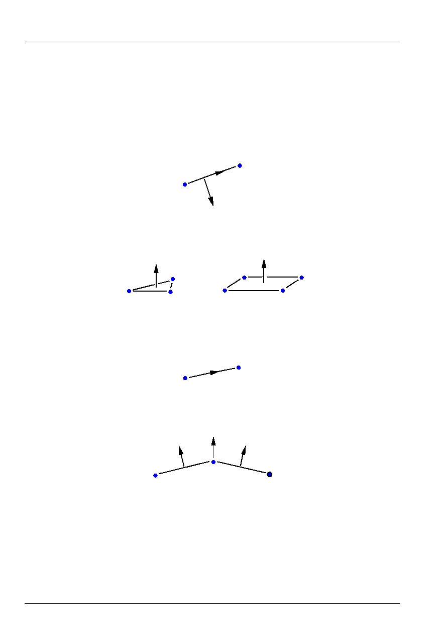
4.1.5 Normals and tangents with the meshs
Normals:
·
SEG2
or
SEG3
in
2D
(co-ordinates defined by
COOR_2D
in the file of mesh with
format Aster). The normal
N
is such as (
N, T
) form a direct reference mark,
T
being carried by
segment directed by the first two nodes of the segment.
1
2
N
T
·
QUAD4
,…,
QUAD9
,
TRIA3
,
TRIA6
in
3D
(co-ordinates defined by
COOR_3D
in the file
of mesh to the format Aster). Orientation of the normal
N
is that corresponding to the direction
direct of the description of the mesh.
2
3
1
1
2
4
3
N
N
Tangents:
Can be specified only if the mesh is of the type
SEG2
or
SEG3
in
2D
. The tangent is that
defined by the segment directed by its the first two nodes.
1
2
T
If
DNOR
(or
DTAN)
are specified, the normal (or the tangent) on a node is the average of
normals or of the tangents of the meshs which have this joint node (except for the elements
quadratic curves where the normal is correctly calculated in any point)
N
N
N

Code_Aster
®
Version
8.2
Titrate:
Operators
AFFE_CHAR_MECA
and
AFFE_CHAR_MECA_F
Date:
22/02/06
Author (S):
X. DESROCHES
Key
:
U4.44.01-I1
Page
:
13/92
Instruction manual
U4.4- booklet: Modeling
HT-62/06/004/A
4.2 Operand
MODEL
MODELE= Mo,
Concept produced by the operator
AFFE_MODELE
where the types of affected finite elements are defined
on the mesh.
4.3 Operand
VERI_NORM
| VERI_NORM=/“YES” [DEFECT]
/
“NOT”
Checking of the orientation of the normals to the surface in 3D and linear meshs in 2D.
If a normal is not outgoing, there is emission of an error message.
4.4 Operand
LIAISON_XFEM
(
AFFE_CHAR_MECA
only)
| LIAISON_XFEM=
“YES”,
During a calculation with method X-FEM [R7.02.12], it is necessary to create a load
additional to cancel some ddls nouveau riches. It is thus necessary imperatively to indicate
LIAISON_XFEM=' OUI' in this specific charge for any calculation X-FEM, as on
the following example:
chxfem
= AFFE_CHAR_MECA (MODEL
= model,
LIAISON_XFEM = “YES”,
)
4.5 Operand
TEMP_CALCULEE
(
AFFE_CHAR_MECA
only)
| TEMP_CALCULEE= temple,
Concept produced by a linear thermal calculation or not linear (
THER_LINEAIRE
[U4.54.01],
THER_NON_LINE
[U4.54.02]) or created starting from values of temperatures affected by
order
CREA_CHAMP
[U4.72.04] key word AFFE or starting from the control
CREA_RESU
[U4.44.12]. If the concept
temple
is of type
cham_no_TEMP_R
then the thermal loading
will be supposed to be constant in time. If it is of type
evol_ther
, possible prolongations
to the terminals of transitory calculation will be supposed to be constant.
4.6 Operand
HYDR_CALCULEE (
AFFE_CHAR_MECA
only)
| HYDR_CALCULEE
=
hydr,
Concept produced by a nonlinear thermal calculation (THER_NON_LINE [U4.54.02]) gathering
fields of hydration and temperature in a concept of the evol_ther type.
4.7 Operand
SECH_CALCULEE (
AFFE_CHAR_MECA
only)
| SECH_CALCULEE
=
sech,
Concept produced by a nonlinear thermal calculation (THER_NON_LINE [U4.54.02]) gathering
fields of drying.
This concept can be either of evol_ther type, or of cham_no_TEMP_R type (if the loading
is constant in time), that is to say of carte_temp_R type (if the loading is constant spaces some and
in time), that is to say of carte_temp_F type (loading function of space).

Code_Aster
®
Version
8.2
Titrate:
Operators
AFFE_CHAR_MECA
and
AFFE_CHAR_MECA_F
Date:
22/02/06
Author (S):
X. DESROCHES
Key
:
U4.44.01-I1
Page
:
14/92
Instruction manual
U4.4- booklet: Modeling
HT-62/06/004/A
4.8 Operand
EPSA_CALCULEE
(
AFFE_CHAR_MECA
only)
| EPSA_CALCULEE
=
epsa,
Anelastic deformations resulting from external software (Cyrano3 Code for example) and
converted into result of the type
evol_noli
by the control
LIRE_RESU
[U7.02.01] option
“EPSA_ELNO”
. This loading is taken into account by
STAT_NON_LINE
[U4.51.03].
4.9 Operand
EVOL_CHAR
(
AFFE_CHAR_MECA
only)
/EVOL_CHAR
= evch,
Evolutionary loadings in the time of the type
“evol_char”
[U5.01.17] produced by
LIRE_RESU
[U7.02.01] and containing fields of pressure, densities of voluminal force in 2D or 3D and
densities of surface force in 2D or 3D.
4.10 Operand
GRAVITY
(
AFFE_CHAR_MECA
only)
| GRAVITY = (G, ap, LP, CP),
Acceleration and direction of gravity. The loading which results from it is form:
where
is the total Cartesian reference mark.
is the definite density like characteristic of material (see operators
DEFI_MATERIAU
[U4.43.01] and
AFFE_MATERIAU
[U4.43.03]
)
.
4.11 Operand
ROTATION
(
AFFE_CHAR_MECA
only)
| ROTATION
= (
, rear, Br, Cr),
Rotational speed and direction of the vector rotation which leads to:
The loading which results from it is:
(
)
OM
where
is the origin of the co-ordinates and
a point running of the structure with
definite density like characteristic of
material (see operators
DEFI_MATERIAU
[U4.43.01] and
AFFE_MATERIAU
[U4.43.03]
)
.
CENTER = (X, y, Z),
If the center is not the origin, one can specify his co-ordinates (X, y, Z).
Important remark:
One can vary in time the rotational speed by breaking up the rotation in way
multiplicative between space loading and evolution in time
, then in
multiplying the LOAD by a multiplying function (key word FONC_MULT) in calculation
transient (DYNA_TRAN_MODAL, DYNA_LINE_TRAN, DYNA_NON_LINE). However, it
is appropriate to pay attention: the loading [
(
)
OM
] being proportional squared
rotational speed,
, it is necessary to affect the square of the evolution in time,
,
behind FONC_MULT.

Code_Aster
®
Version
8.2
Titrate:
Operators
AFFE_CHAR_MECA
and
AFFE_CHAR_MECA_F
Date:
22/02/06
Author (S):
X. DESROCHES
Key
:
U4.44.01-I1
Page
:
15/92
Instruction manual
U4.4- booklet: Modeling
HT-62/06/004/A
4.12 Key word
DDL_IMPO
4.12.1 Drank
Key word factor usable to impose, with nodes introduced by one (at least) of the key words:
ALL, NODE, GROUP_NO, MESH, GROUP_MA, one or more values of displacement (or of
certain associated sizes).
According to the name of the operator called, the values are provided directly (
AFFE_CHAR_MECA
) or
via a concept
function
(
AFFE_CHAR_MECA_F)
.
4.12.2 Syntax
·
for
AFFE_CHAR_MECA
|
DDL_IMPO=_F
(
/ALL =
“YES”,
/
NODE
=
lno
, [l_noeud]
/
GROUP_NO=
lgno,
[l_gr_noeud]
/
NET
=
lma
, [l_maille]
/
GROUP_MA=
lgma,
[l_gr_maille]
/
|
DX =
ux,
[R]
|
DY =
uy,
[R]
|
DZ =
uz,
[R]
|
DRX
=
X,
[R]
|
DRY
=
y,
[R]
|
DRZ
=
Z,
[R]
|
GRX
= G, [R]
|
PRES= p, [R]
|
PHI
=
, [R]
|
TEMP= T, [R]
|
PRE1=
pr1
, [R]
|
PRE2=
pr2
, [R]
|
GONF=
treps,
[R]
/
LIAISON=
“EMBEDS”
)
The list of the others ddls being able to be imposed is:
UI2… UI6, UO2… UO6, VI2… VI6, VO2… VO6,
WI2… VI6, WO2… WO6,
WO,
WI1,
WO1
[R]
·
for
AFFE_CHAR_MECA_F
|
DDL_IMPO=_F
(
/ALL =
“YES”,
/
NODE
=
lno
, [l_noeud]
/
GROUP_NO=
lgno,
[l_gr_noeud])
/
NET
=
lma
, [l_maille]
/
GROUP_MA=
lgma,
[l_gr_maille]
/
|
DX =
ux,
[function]
|
DY =
uyf, [function]
|
DZ =
uzf, [function]
|
DRX
=
xf, [function]
|
DRY
=
yf, [function]
|
DRZ
=
zf, [function]
|
GRX
=
gf
,
[function]
|
PRES=
PF
,
[function]
|
PHI
=
F,
[function]
|
TEMP=
Tf
,
[function]
|
PRE1=
pr1f,
[function]
|
PRE2=
pr2f,
[function]
/
LIAISON=
“EMBEDS”
)
Code_Aster
®
Version
8.2
Titrate:
Operators
AFFE_CHAR_MECA
and
AFFE_CHAR_MECA_F
Date:
22/02/06
Author (S):
X. DESROCHES
Key
:
U4.44.01-I1
Page
:
16/92
Instruction manual
U4.4- booklet: Modeling
HT-62/06/004/A
4.12.3 Operands
| DDL_IMPO
All the specified values are defined in the TOTAL reference mark of definition of the mesh.
·
DX
=
ux
or
uxf
·
DY
=
uy
or
uyf
Value of the component of displacement in imposed translation
on the specified nodes
·
DZ
=
uz
or
uzf
Only if the specified nodes belong to discrete elements of
translation - rotation, of beam or hull:
·
DRX
=
X
or
xf
·
DRY
=
y
or
yf
Value of the component of displacement in rotation imposed on
specified nodes
·
DRZ
=
Z
or
zf
Only if the specified nodes belong to elements of beam
“POU_D_TG”
:
·
GRX
= G or G
F
Value of the roll of the beam
Only if the specified nodes belong to elements fluid or fluid structure:
·
NEAR
=
p
or
PF
Acoustic pressure in the fluid (modeling
“3d_FLUIDE”
)
·
PHI
=
or
F
Potential of displacements of the fluid (modelings
“3d_FLUIDE”
and
“FLUI_STRU”
)
Only if the specified nodes belong to elements of free face:
·
DZ
=
uz
or
uzf
Imposed displacement of the free face (modeling
“2d_FLUI_PESA”)
·
PHI
=
or
F
Potential of displacements of the fluid (modeling
“2d_FLUI_PESA”)
Only if the specified nodes belong to elements THM:
·
PRES= p
Pressure of the interstitial fluid (modelings
“3d_JOINT_CT”
)
·
TEMP= T
Temperature (modelings
“”
with
= 3D or AXIS or D_PLAN
YYYY = THM or THHM or THH)
·
PRE1= p1
Capillary pressure or pressure of the fluid or gas
(modelings
“”
with
= 3D or AXIS or D_PLAN
YYYY = THM or THHM or THH or HM or HHM)
·
PRE2= p2
Pressure of gas
(modelings
“”
with
= 3D or AXIS or D_PLAN
YYYY = THH or THHM or HHM)
Only if the specified nodes belong to elements “PIPE”.
These elements have 15 DDL of hull:
U: roll
V, W: ovalization
I: “in plane”
O: “out off planes”
That is to say:
·
UI2 VI2 WI2 UO2 VO2 WO2
DDL related to mode 2
·
UI3 VI3 WI3 UO3 VO3 WO3
DDL related to mode 3
·
WO WI1 WO1
DDL of swelling and mode 1 on W

Code_Aster
®
Version
8.2
Titrate:
Operators
AFFE_CHAR_MECA
and
AFFE_CHAR_MECA_F
Date:
22/02/06
Author (S):
X. DESROCHES
Key
:
U4.44.01-I1
Page
:
17/92
Instruction manual
U4.4- booklet: Modeling
HT-62/06/004/A
Only if the specified nodes belong to elements “TUYAU_6M'.
·
UI4 VI4 WI4 UO4 VO4 WO4
DDL related to mode 4
·
UI5 VI5 WI5 UO5 VO5 WO5
DDL related to mode 5
·
UI6 VI6 WI6 UO6 VO6 WO6
DDL related to mode 6
Only if the specified nodes belong to elements “XXX_INCO”.
·
GONF
swelling
CONNECTION = “EMBEDS”
Allows to embed directly nodes, a.c. D. to force with zero them
ddl
of translation and of
rotation. Others
ddl
are not modified.
4.12.4 Checks and recommendations
It is checked that it
ddl
specified exists in this node for the elements affected in
MODEL
with
meshs which contain the node.
However, if the same boundary condition is specified twice by two calls to
AFFE_CHAR_MECA
(for example, with two values of imposed displacement), that led to one
singular matrix.
If it is specified twice (or more) in only one call to
AFFE_CHAR_MECA
, the rule of overload
apply and a message of alarm (indicating the overload) is transmitted.

Code_Aster
®
Version
8.2
Titrate:
Operators
AFFE_CHAR_MECA
and
AFFE_CHAR_MECA_F
Date:
22/02/06
Author (S):
X. DESROCHES
Key
:
U4.44.01-I1
Page
:
18/92
Instruction manual
U4.4- booklet: Modeling
HT-62/06/004/A
4.13 Key word
FACE_IMPO
4.13.1 Drank
Key word factor usable to impose, with all the nodes of a face defined by a mesh or one
group meshs, one or more values of displacement (or certain associated sizes).
According to the name of the operator called, the values are provided directly (
AFFE_CHAR_MECA
) or
via a concept
function
(
AFFE_CHAR_MECA_F)
.
4.13.2 Syntax
·
for
AFFE_CHAR_MECA
|
FACE_IMPO=_F
(
/MESH =
lma, [l_maille]
/
GROUP_MA=
lgma,
[l_gr_maille]
/
|
DX =
ux, [R]
|
DY =
uy, [R]
|
DZ =
uz, [R]
|
DRX
=
X, [R]
|
DRY
=
y, [R]
|
DRZ
=
Z, [R]
|
GRX
=
G
,
[R]
|
PRES=
p
,
[R]
|
PHI
=
, [R]
|
TEMP=
T
,
[R]
|
PRE1=
pr1
,
[R]
|
PRE2=
pr2
,
[R]
/
|
DNOR=
one
,
[R]
|
DTAN=
C
,
[R]
)
·
for
AFFE_CHAR_MECA_F
|
FACE_IMPO=_F
(
/MESH =
lma, [l_maille]
/
GROUP_MA=
lgma,
[l_gr_maille]
/
|
DX =
uxf, [function]
|
DY =
uyf, [function]
|
DZ =
uzf, [function]
|
DRX
=
xf, [function]
|
DRY
=
yf, [function]
|
DRZ
=
zf, [function]
|
GRX
=
gf
,
[function]
|
PRES=
PF
,
[function]
|
PHI
=
F, [function]
|
TEMP=
Tf
,
[function]
|
PRE1=
pr1f,
[function]
|
PRE2=
pr2f,
[function]
/
|
DNOR=
one
,
[function]
|
DTAN=
C
,
[function]
)

Code_Aster
®
Version
8.2
Titrate:
Operators
AFFE_CHAR_MECA
and
AFFE_CHAR_MECA_F
Date:
22/02/06
Author (S):
X. DESROCHES
Key
:
U4.44.01-I1
Page
:
19/92
Instruction manual
U4.4- booklet: Modeling
HT-62/06/004/A
4.13.3 Operands
/
|
DX =
|
DY =
|
DZ =
|
DRX
=
|
DRY
=
|
DRZ
=
|
GRX
=
|
PRES=
|
PHI
=
|
TEMP=
|
PRE1=
|
PRE2=
The components, imposed on all the nodes belonging to the specified meshs, are
defined in the reference mark
TOTAL
of definition of the mesh.
The faces considered are made up:
·
maybe of
TRIA3
,
TRIA6
,
QUAD4
,
QUAD8
,
QUAD9
in dimension 3,
·
maybe of
SEG2
or
SEG3
in dimension 2 (the face is reduced on a board).
Note:
Components of displacement in rotation
DRX, DRY, DRZ
cannot intervene
that on nodes which belong to elements of beam or hull (see
DDL_IMPO
[§4.10]),
the component
GRX
on elements of beam
“POU_D_TG”
,
components
NEAR
and
PHI
on elements of modelings
“3d_FLUIDE”
and
“FLUI_STRU”
, components
DZ
and
PHI
on elements of modeling
“2d_FLUI_PESA”
.
Components TEMP, PRE1, PRE2 on elements of modeling THM.
/
|
DNOR
=
|
DTAN
=
The imposed components are defined according to the normal or the tangent with a mesh
(local reference mark).
DNOR
: normal component (see [U4.44.01 §4.1]),
DTAN
: tangential component (see [U4.44.01 §4.1]).

Code_Aster
®
Version
8.2
Titrate:
Operators
AFFE_CHAR_MECA
and
AFFE_CHAR_MECA_F
Date:
22/02/06
Author (S):
X. DESROCHES
Key
:
U4.44.01-I1
Page
:
20/92
Instruction manual
U4.4- booklet: Modeling
HT-62/06/004/A
4.14 Key word
LIAISON_DDL
4.14.1 Drank
Key word factor usable to define a linear relation between degrees of freedom of two or
several nodes.
According to the name of the operator called, the values are provided directly (
AFFE_CHAR_MECA
) or
via a concept
function
(
AFFE_CHAR_MECA_F)
.
4.14.2 Syntax
·
for
AFFE_CHAR_MECA
LIAISON_DDL=_F (
/NODE =
lno, [l_noeud]
/
GROUP_NO
= lgno,
[l_gr_noeud]
DDL=
|
“DX”,
|
“DY”,
|
“DZ”,
|
“DRX”,
|
“DRY”,
|
“DRZ”,
COEF_MULT
=
I, [l_R]
COEF_IMPO
=
, [R]
)
·
for
AFFE_CHAR_MECA_F
LIAISON_DDL=_F (
/NODE =
lno, [l_noeud]
/
GROUP_NO
=
lgno,
[l_gr_noeud]
DDL=
|
“DX”,
|
“DY”,
|
“DZ”,
|
“DRX”,
|
“DRY”,
|
“DRZ”,
COEF_MULT
=
I, [l_R]
COEF_IMPO
=
F, [function]
)
4.14.3 Operands
GROUP_NO
or
NODE
: list nodes NR
I
(I = 1, R) ordered in a natural way:
·
in the order of the list of groups of nodes, and for each group of nodes, in the order
of definition of the group by
GROUP_NO
,
·
in the order of the list of nodes for
NODE
.
DDL
: list
ddl
(I = 1, R) of R texts taken among:
“DX”, “DY”, “DZ”, “DRX”,
“DRY”,
“DRZ”
COEF_MULT
: list
(I = 1, R) of coefficients (of real type for
AFFE_CHAR_MECA
and for
AFFE_CHAR_MECA_F
).
COEF_IMPO
: coefficient
for
AFFE_CHAR_MECA
, function of time for
AFFE_CHAR_MECA_F
.
The following kinematic condition will be applied:

Code_Aster
®
Version
8.2
Titrate:
Operators
AFFE_CHAR_MECA
and
AFFE_CHAR_MECA_F
Date:
22/02/06
Author (S):
X. DESROCHES
Key
:
U4.44.01-I1
Page
:
21/92
Instruction manual
U4.4- booklet: Modeling
HT-62/06/004/A
4.14.4 Precautions of use
4.14.4.1 Components in rotation
Components of displacement in rotation
DRX, DRY, DRZ
can intervene only in
combinations only assigned to nodes which belong to discrete elements of
translation-rotation, of beam or hull (see
DDL_IMPO
: cf [§4.10]).
4.14.4.2 Linear relation between the ddl of the same node
In this particular case, one will repeat behind the key word
NODE
the name of the node as many time as there is
of
ddl
in the relation. Example: to impose
on the N1 node, one will write:
LIAISON_DDL =_F (NODE = (“N1”, “N1”),
DDL = (“DX”, “DY”),
COEF_MULT
=
(1.,
- 1.),
COEF_IMPO
=
0.,
)
4.14.4.3 Linear relation between groups of nodes
It is important to note that with an occurrence of the key word factor
LIAISON_DDL
corresponds one and one
only linear relation.
If one wants to impose the same relation between 2 groups of nodes
GRN01
and
GRN02
(even displacement
node with node for example) one cannot write:
LIAISON_DDL = _F (GROUP_NO = (“GRNO1”, “GRNO2”),
DDL = (“DX” “DX”),
COEF_MULT
=
(1.
,
- 1.),
COEF_IMPO
=
0.,
)
This writing has direction only if
GRNO1
and
GRNO2
contain each one one node. It will be necessary
in the case above to clarify each linear relation, node by node, or to use LIAISON_GROUP
[§4.14] which makes it possible to condense the writing of same linear relations between two groups of nodes
in opposite.

Code_Aster
®
Version
8.2
Titrate:
Operators
AFFE_CHAR_MECA
and
AFFE_CHAR_MECA_F
Date:
22/02/06
Author (S):
X. DESROCHES
Key
:
U4.44.01-I1
Page
:
22/92
Instruction manual
U4.4- booklet: Modeling
HT-62/06/004/A
4.15 Key word
LIAISON_OBLIQUE
4.15.1 Drank
Key word factor usable to apply, with nodes or groups of nodes, the same value of
displacement definite component by component in an unspecified oblique reference mark.
According to the name of the operator called, the values are provided directly (
AFFE_CHAR_MECA
) or
via a concept
function
(
AFFE_CHAR_MECA_F)
.
4.15.2 Syntax
·
for
AFFE_CHAR_MECA
|
LIAISON_OBLIQUE
=_F
(
/NODE =
No,
[node]
/
GROUP_NO
= gno
, [gr_noeud]
|
DX
=
ux
,
[R]
|
DY
=
uy
,
[R]
|
DZ
=
uz
,
[R]
|
DRX
=
X,
[R]
|
DRY
=
y,
[R]
|
DRZ
=
Z,
[R]
ANGL_NAUT =
(
,
,
)
, [l_R]
)
·
for
AFFE_CHAR_MECA_F
I
LIAISON_OBLIQUE
=_F
(
/NODE =
No,
[node]
/
GROUP_NO
= gno
, [gr_noeud]
|
DX =
uxf, [function]
|
DY =
uyf, [function]
|
DZ =
uzf, [function]
|
DRX
=
xf, [function]
|
DRY
=
yf, [function]
|
DRZ
=
zf, [function]
ANGL_NAUT =
(
)
, [l_R]
)
4.15.3 Operands
|
LIAISON_OBLIQUE
·
DX
=
ux
or
uxf
·
DY
=
uy
or
uyf
·
DZ
=
uz
or
uzf
Value of the component of displacement in translation in
oblique reference mark imposed on the specified nodes
Only if the specified nodes belong to discrete elements of
translation-rotation, of beam or hull.
·
DRX
=
X
or
xf
·
DRY
=
y
or
yf
·
DRZ
=
Z
or
zf
Value of the component of displacement in rotation in
oblique reference mark imposed on the specified nodes
ANGL_NAUT
=
(
,
,
)
,
nautical angles
defined in degrees, are the angles allowing to pass from
identify
TOTAL
of definition of the co-ordinates of the nodes to a reference mark obliques
unspecified (see AFFE_CARA_ELEM [U4.42.01]).

Code_Aster
®
Version
8.2
Titrate:
Operators
AFFE_CHAR_MECA
and
AFFE_CHAR_MECA_F
Date:
22/02/06
Author (S):
X. DESROCHES
Key
:
U4.44.01-I1
Page
:
23/92
Instruction manual
U4.4- booklet: Modeling
HT-62/06/004/A
4.15.4 Checking
It is checked that it
ddl
specified exists in this node for the elements affected in
MODEL
with
meshs which contain the node.
4.15.5 Limitation
Into an occurrence of the key word factor, one can introduce for the moment one node or one
only group of nodes containing one node.

Code_Aster
®
Version
8.2
Titrate:
Operators
AFFE_CHAR_MECA
and
AFFE_CHAR_MECA_F
Date:
22/02/06
Author (S):
X. DESROCHES
Key
:
U4.44.01-I1
Page
:
24/92
Instruction manual
U4.4- booklet: Modeling
HT-62/06/004/A
4.16 Key word
LIAISON_GROUP
4.16.1 Drank
Key word factor usable to define the same linear relation between certain degrees of freedom of
couples of nodes, these couples of nodes being obtained while putting in opposite two lists of meshs
or of nodes [§4.14.5].
According to the name of the operator called, the values are provided directly (
AFFE_CHAR_MECA
) or
via a concept
function
(
AFFE_CHAR_MECA_F
).
4.16.2 Syntax
·
for
AFFE_CHAR_MECA
LIAISON_GROUP=_F
(
/
/MAILLE_1 = lma1, [l_maille]
/
GROUP_MA_1 =
lgma1,
[l_gr_maille]
/MAILLE_2 = lma2, [l_maille]
/
GROUP_MA_2 =
lgma2,
[l_gr_maille]
/
/NOEUD_1 = lno1, [l_noeud]
/
GROUP_NO_1 =
lgno1,
[l_gr_noeud]
/NOEUD_2 = lno2, [l_noeud]
/
GROUP_NO_2 =
lgno2,
[l_gr_noeud]
/
SANS_NOEUD =
lno
, [l_noeud]
/
SANS_GROUP_NO
=
lgno,
[l_gr_noeud]
DDL_1 =
/
|
“DX”,
|
“DY”,
|
“DZ”,
|
“DRX”,
|
“DRY”,
|
“DRZ”,
/“DNOR”,
DDL_2 =
/
|
“DX”,
|
“DY”,
|
“DZ”,
|
“DRX”,
|
“DRY”,
|
“DRZ”,
/“DNOR”,
COEF_MULT_1 =
1i
, [l_R]
COEF_MULT_2 =
2i
, [l_R]
COEF_IMPO
=
, [R]
SUMMIT
=
“YES”,
CENTER
=
Lr
,
[l_R]
ANGL_NAUT
=
Lr
,
[l_R]
TRAN =
Lr
,
[l_R]
)

Code_Aster
®
Version
8.2
Titrate:
Operators
AFFE_CHAR_MECA
and
AFFE_CHAR_MECA_F
Date:
22/02/06
Author (S):
X. DESROCHES
Key
:
U4.44.01-I1
Page
:
25/92
Instruction manual
U4.4- booklet: Modeling
HT-62/06/004/A
·
for
AFFE_CHAR_MECA_F
LIAISON_GROUP=_F
(
/
/MAILLE_1 = lma1, [l_maille]
/
GROUP_MA_1 =
lgma1,
[l_gr_maille]
/MAILLE_2 = lma2, [l_maille]
/
GROUP_MA_2 =
lgma2,
[l_gr_maille]
/
/NOEUD_1 = lno1, [l_noeud]
/
GROUP_NO_1 =
lgno1,
[l_gr_noeud]
/NOEUD_2 = lno2, [l_noeud]
/
GROUP_NO_2 =
lgno2,
[l_gr_noeud]
/
SANS_NOEUD =
lno
, [l_noeud]
/
SANS_GROUP_NO
=
lgno,
[l_gr_noeud]
DDL_1 =
/
|
“DX”,
|
“DY”,
|
“DZ”,
|
“DRX”,
|
“DRY”,
|
“DRZ”,
/“DNOR”,
DDL_2 =
/
|
“DX”,
|
“DY”,
|
“DZ”,
|
“DRX”,
|
“DRY”,
|
“DRZ”,
/“DNOR”,
COEF_MULT_1 =
1i
, [l_R]
COEF_MULT_2 =
2i
, [l_R]
COEF_IMPO
=
F,
[function]
SUMMIT
=
“YES”,
CENTER
=
Lr
,
[l_R]
ANGL_NAUT
=
Lr
,
[l_R]
TRAN =
Lr
,
[l_R]
)
4.16.3 Operands
/
/GROUP_MA_1
=
/
MAILLE_1
=
These operands define the first list of meshs in relation (noted
1
).
/GROUP_MA_2
=
/
MAILLE_2
=
These operands define the second list of meshs in relation (noted
2
).
/GROUP_NO_1
=
/
NOEUD_1
=
These operands define the first list of nodes in relation.
/GROUP_NO_2
=
/
NOEUD_2
=
These operands define the second list of nodes in relation.
The two lists must have the same length.
Code_Aster
®
Version
8.2
Titrate:
Operators
AFFE_CHAR_MECA
and
AFFE_CHAR_MECA_F
Date:
22/02/06
Author (S):
X. DESROCHES
Key
:
U4.44.01-I1
Page
:
26/92
Instruction manual
U4.4- booklet: Modeling
HT-62/06/004/A
/SANS_GROUP_NO
=
/
SANS_NOEUD
=
These operands make it possible to remove list of the couples of nodes in opposite
[§4.14.5] all the couples of which at least one of the nodes belongs to the list of nodes
described by these operands.
That makes it possible to avoid the accumulation of linear relations on the same node with the course
various repetitions of the key word factor
LIAISON_GROUP,
what leads the majority
time with a singular matrix.
DDL_1 (_2) =
The argument of
DDL_1
or
_2
must be a list of texts taken among (
DX', “DY”, “DZ”,
“DRX”, “DRY”, “DRZ”)
or
“DNOR”
.
COEF_MULT_1 (
resp.
COEF_MULT_2) =
List realities dimensioned exactly with the number of degrees of freedom declared in
DDL_1
(resp.
DDL_2
) corresponding to the multiplying coefficients of the linear relation.
COEF_IMPO =
Coefficient of blocking of the linear relation:
: reality for
AFFE_CHAR_MECA
: function for
AFFE_CHAR_MECA_F
The operands CENTERS/ANGL_NAUT/TRAN make it possible to define a transformation
virtual (rotation and/or translation) approximate of
1
in
2
in order to ensure the bijectivity of
the function opposite [§4.14.5].
The control carries out initially rotation, then the translation.
CENTER
=
co-ordinates of the center of rotation (in the total reference mark)
ANGL_NAUT
=
nautical angles defining rotation (in degrees)
TRAN =
components of the vector translation
Note:
·
It is checked that the ddl specified in these operands exist for each one of
nodes of the elements affected in
MODEL
with the meshs which contain it
node,
·
to use the argument
“DNOR”
, it is obligatory to have declared the edges with
the aid of meshs and that the calculation of a normal on these meshs is possible.
SUMMIT = “YES”
When the meshs of edge are quadratic (thus
SEG3
) the use of
SUMMIT:
“YES”
force the algorithm of pairing to associate the nodes of
SEG3
with others
nodes, and mediums of
SEG3
in other mediums. In the case of fine mesh, that
allows in certain cases to avoid the problems of conflicts of opposite.
4.16.4 Example of use
One wants to impose a cyclic condition of repetitivity (even normal displacement) between FACE 1 and
FACE 2 of the geometry below:
0
FACE
1
FACE 2

Code_Aster
®
Version
8.2
Titrate:
Operators
AFFE_CHAR_MECA
and
AFFE_CHAR_MECA_F
Date:
22/02/06
Author (S):
X. DESROCHES
Key
:
U4.44.01-I1
Page
:
27/92
Instruction manual
U4.4- booklet: Modeling
HT-62/06/004/A
Let us suppose that FACE 1 (resp. FACE 2) is made up of the list of meshs lma1 (resp. lma2).
One wants to write the following linear relations:
node of face 1 of opposite
where nbno is the number of nodes of face 1 (and of face 2).
The data of LIAISON_GROUP will be written:
LIAISON_GROUP=_F (MAILLE_1 = lma1,
MAILLE_2
=
lma2,
DDL_1
=
“DNOR”,
DDL_2
=
“DNOR”,
COEF_MULT_1
=
1.,
COEF_MULT_2
=
- 1.,
COEF_IMPO
=
0,
CENTER
=
(X0, Y0, Z0),
ANGL_NAUT
=
(
, 0., 0.),
)
4.16.5 Determination of the couples of nodes in opposite
It is in the same way made that in
AFFE_CHAR_THER
.
Initially, one draws up the two lists of nodes to be put in opposite (IE to be paired),
for each occurrence of the key word factor
LIAISON_GROUP
:
·
for the key words
GROUP_NO_1
and
GROUP_NO_2
, they are the nodes constituting them
groups of nodes,
·
for the key words
GROUP_MA_1
and
GROUP_MA_2
, they are the nodes of the meshs
setting up the groups of meshs.
The redundancies being eliminated, the two lists of nodes obtained must have the same one
length.
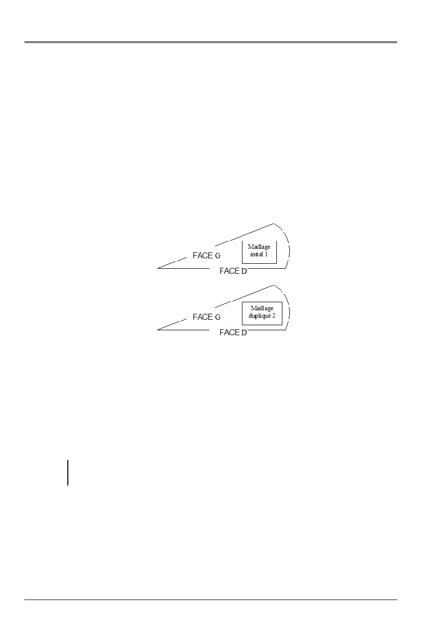
The determination of the couples of nodes in opposite is done in several stages:
·
for each N1 node of the first list, one seeks the node image N2 = F (N1) of
second list. If F is not injective (a node N2 is the image of two distinct nodes N1
and N1'), the error message according to is emitted:
<F> <AFFE_CHAR_MECA> <PACOAP> CONFLICT IN WITH RESPECT TO THE NODES
THE NODE N2 EAST IT WITH RESPECT TO THE NODES N1 AND N1'
·
for each node N2 of the second list, one seeks the node N1 image = G (N2) of
first list. If G is not injective (a N1 node of two distinct nodes N2 is the image and
N2'), the error message according to is emitted:
<F> <AFFE_CHAR_MECA> <PACOAP> CONFLICT IN WITH RESPECT TO THE NODES
THE NODE N1 EAST IT WITH RESPECT TO THE NODES N2 AND N2'
·
it is checked that G = F
1
, i.e. the couples obtained by the stages has) and b) are them
same (one wants to have a bijection F between the two lists of nodes). If F is not surjective,
the error message according to is transmitted:
<F> <AFFE_CHAR_MECA> <PACOAP> CONFLICT IN OPPOSITE GENERATE
SUCCESSIVELY FROM LISTS LIST1 AND LIST2
The NODE OF the FIRST N1 LIST IS NOT the IMAGE Of ANY NODE BY
CORRESPONDENCE
OPPOSITE

Code_Aster
®
Version
8.2
Titrate:
Operators
AFFE_CHAR_MECA
and
AFFE_CHAR_MECA_F
Date:
22/02/06
Author (S):
X. DESROCHES
Key
:
U4.44.01-I1
Page
:
28/92
Instruction manual
U4.4- booklet: Modeling
HT-62/06/004/A
For a node NR given, one calls node image F (NR) the node of the other list of nodes which
carry out the minimum of the distance with NR. to facilitate pairing, in particular in the case of
particular geometries (where borders
1
and
2
could “almost” result one from the other
by the composition of a translation and a rotation), one makes it possible to do one
virtual geometrical transformation of the first group of nodes (translation and rotation before
to calculate the distances (key words
TRAN
,
CENTER
and
ANGL_NAUT
).
For each occurrence of the key word factor
LIAISON_GROUP
, one builds the list thus of
new couples in opposite. When all the occurrences were swept, list is removed
couples in double.
Note:
In the couples of nodes in opposite, the command of the nodes is important. If for
first occurrence of
LIAISON_GROUP
, a node NR belonged to the first group of
nodes and a node M with the second group of node, and that for the second occurrence
of
LIAISON_GROUP
, it is the reverse, one will obtain with the exit pairing the couples
(NR, M) and (M, NR). They will not be eliminated during detection of the redundancies; by
against, the matrix obtained will be singular. Thus, one advises to keep same logic
during the description of the edges in opposite.
Code_Aster
®
Version
8.2
Titrate:
Operators
AFFE_CHAR_MECA
and
AFFE_CHAR_MECA_F
Date:
22/02/06
Author (S):
X. DESROCHES
Key
:
U4.44.01-I1
Page
:
29/92
Instruction manual
U4.4- booklet: Modeling
HT-62/06/004/A
4.17 Key word
LIAISON_MAIL
4.17.1 Drank
Key word factor usable to define linear relations allowing “to restick” two “edges” of one
structure.
The characteristic of this key word (compared to LIAISON_GROUP for example) is to make it possible to bind
displacements of unconstrained nodes on the mesh. Mesh of FACE 1 and FACE 2
can be incompatible.
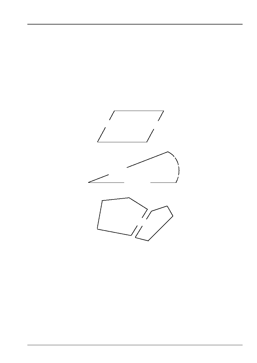
Examples:
) a condition of interval has (study of an airframe of homogenization)
FACE 1
FACE 2
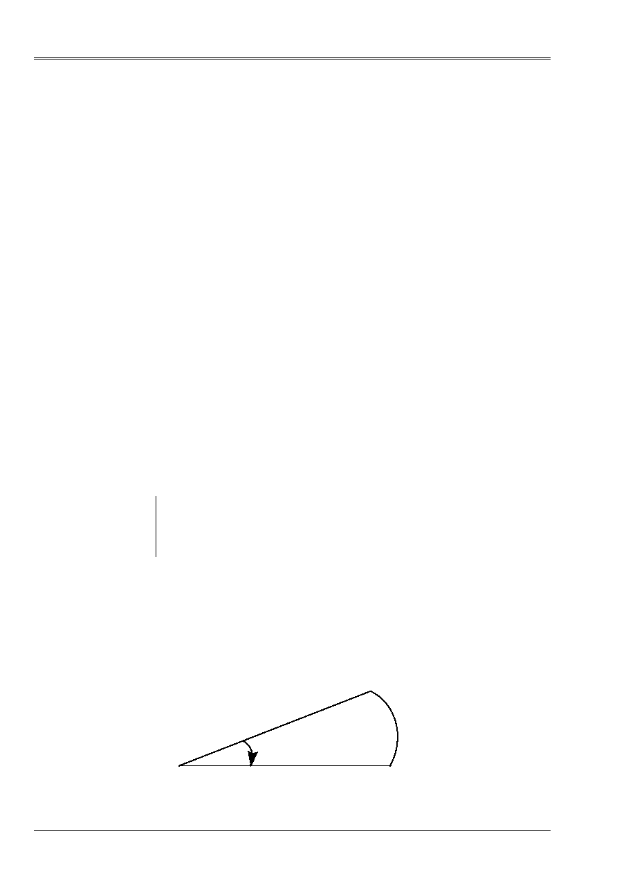
b) a cyclic condition of repetitivity
FACE 1
FACE 2
c) a condition of simple sticking together
FACE 2
FACE 1
In the continuation of this paragraph, one will speak about the face “slave” (FACE 2) and about the face “Master”
(FACE 1).
The “sticking together” of the 2 faces will be done by writing of linear relations between the ddls of the 2 faces.
Displacements of the nodes of the face slave will be connected to displacements of their projections
on the face Master. For each node of the face slave, one will write 2 (in 2D) or 3 (in 3D) relations
linear.
If FACE 1 and FACE 2 are not geometrically confused but that there is a isometry
(rotation + translation) between the two, the user must define this isometry (that which transforms
FACE 2 opposite 1).
An application of this functionality is for example the sticking together of a formed mesh of elements
linear (P1) on another quadratic mesh (P2). In this case it is rather advised to choose
like face “slave” the quadratic face.
Code_Aster
®
Version
8.2
Titrate:
Operators
AFFE_CHAR_MECA
and
AFFE_CHAR_MECA_F
Date:
22/02/06
Author (S):
X. DESROCHES
Key
:
U4.44.01-I1
Page
:
30/92
Instruction manual
U4.4- booklet: Modeling
HT-62/06/004/A
4.17.2 Syntax (in AFFE_CHAR_MECA only)
LIAISON_MAIL =_F
(
|
GROUP_NO_ESCL
=
lgno2
,
[l_gr_noeud]
|
NOEUD_ESCL =
lno2,
[l_noeud]
|
GROUP_MA_ESCL
=
lgma2
,
[l_gr_maille]
|
MAILLE_ESCL
=
lma2,
[l_maille]
|
GROUP_MA_MAIT
=
lgma1
,
[l_gr_maille]
|
MAILLE_MAIT
=
lma1,
[l_maille]
|
CENTER
=
(teststemxç,
teststemyç,
[zc]),
[l_R]
ANGL_NAUT
= (alpha, [beta, gamma]),
[l_R]
|
TRAN =
(tx,
ty,
[tz]),
[l_R]
DDL_MAIT
=
“DNOR”,
DDL_ESCL
=
“DNOR”,
ELIM_MULT
=
/
“NOT”,
[DEFECT]
/
“YES”,
)
4.17.3 Operands
4.17.3.1 GROUP_NO_ESCL/NOEUD_ESCL/GROUP_MA_ESCL/MAILLE_ESCL
These key words make it possible to define the whole of the nodes of the face slave. One takes all them
nodes specified by key words GROUP_NO_ESCL and NOEUD_ESCL more all nodes carried by
meshs specified by key words GROUP_MA_ESCL and MAILLE_ESCL.
Note:
When one wants to restick only normal displacements of the faces (cf key words DDL_MAIT and
DDL_ESCL), it is necessary to be able to determine the normal direction of the faces. The normal direction is
calculated on the face slave. It is thus necessary in this case to use key words GROUP_MA_ESCL and
MAILLE_ESCL with meshs of the type “facets”.
4.17.3.2 GROUP_MA_MAIT/MAILLE_MAIT
These key words make it possible to define the whole of the meshs where they with respect to the nodes will be sought
face slave.
Caution:
In 3D, one should not give meshs of surface, but the voluminal meshs adjacent with
face. The specified meshs are “candidates” for the search of the points opposite. One can
in giving too much, that is not awkward.
In the same way, in 2D, the meshs “Masters” must be surface (QUAD, SORTED) and nonlinear
4.17.3.3 CENTER/ANGL_NAUT/TRAN
These key words make it possible to define the geometrical transformation (rotation and/or translation)
allowing to pass from the face main slave to the face.
If these key words miss, it is that the geometrical transformation is “the identity” i.e.
the faces Master and slave are geometrically confused.
It should be noted that the program carries out initially rotation and then the translation. Caution: the direction
transformation is slave --> main.
4.17.3.4 DDL_MAIT/DDL_ESCL
If one wants to restick only normal displacements with the faces, it is necessary to specify:
DDL_MAIT = “DNOR”
DDL_ESCL = “DNOR”
Note:
The normal direction is calculated on the face slave (it is necessary to give meshs of breakage). This
normal direction is transformed by the possible rotation of the geometrical transformation for
to determine the normal direction on the face Master.

Code_Aster
®
Version
8.2
Titrate:
Operators
AFFE_CHAR_MECA
and
AFFE_CHAR_MECA_F
Date:
22/02/06
Author (S):
X. DESROCHES
Key
:
U4.44.01-I1
Page
:
31/92
Instruction manual
U4.4- booklet: Modeling
HT-62/06/004/A
4.17.3.5 ELIM_MULT= “YES”/“NOT” (defect)
This key word is used to solve the difficulty which can arise when several surfaces are restuck
adjacent slaves (i.e who have one or more common nodes).
Let us imagine for example that one writes (in 2D):
LIAISON_MAIL= (
_F (GROUP_MA_ESCL=' LIGNE_AB', GROUP_MAIT=…)
_F (GROUP_MA_ESCL=' LIGNE_BC', GROUP_MAIT=…)
If the user forces ELIM_MULT=' OUI', the program will treat each occurrence of LIAISON_MAIL
in way independent. The node B, pertaining to LIGNE_AB and LIGNE_BC will be eliminated 2 times and it
is unfortunately probable that calculation will stop during the factorization of the matrix with
message “Pivot almost no one…” because the linear relations generated by LIAISON_MAILLE are
redundant.
Most of the time, defect (ELIM_MULT=' NON') is the good choice. The only case where the user
could use ELIM_MULT=' OUI' is that of the use of key word DDL_ESCL=' DNOR' bus if in
the 2 occurrences, the normals “slaves” are not the same ones, elimination is not redundant.
Code_Aster
®
Version
8.2
Titrate:
Operators
AFFE_CHAR_MECA
and
AFFE_CHAR_MECA_F
Date:
22/02/06
Author (S):
X. DESROCHES
Key
:
U4.44.01-I1
Page
:
32/92
Instruction manual
U4.4- booklet: Modeling
HT-62/06/004/A
4.18 Key word
LIAISON_CYCL
4.18.1 Drank
Key word factor usable to define the linear relations allowing to impose conditions of
cyclic symmetry with taking into account of a dephasing. It is mainly dedicated to being used in
the restrictive framework of dynamic calculation with cyclic symmetry.
The characteristic of this key word (with the image of LIAISON_MAIL) is to make it possible to bind displacements
unconstrained nodes on the mesh. The mesh of FACE G and FACE D can be
incompatible.
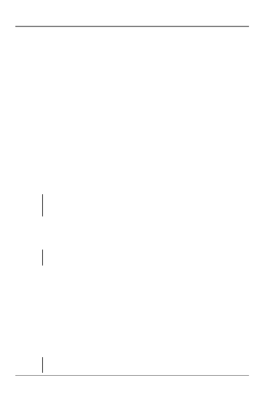
The cyclic condition of repetitivity applied within the framework of dynamics is based on
method of duplication of mesh. The operator thus leaves on the postulate that the initial mesh one
sector is duplicated in two mesh identical to the image of the following figure.
In the continuation of this paragraph, one will speak about the face “slave” and the face “Master”. The “sticking together”
of the 2 faces will be done by writing of linear relations between the ddls of the 2 faces.
Displacements of the nodes of the face slave will be connected to displacements of their projections
on the face Master. For each node of the face slave, one will write 2 (in 2D) or 3 (in 3D) relations
linear.
If FACE G and FACE D are not geometrically confused but that there is a isometry
(rotation + translation) between the two, the user must define this isometry (that which transforms
FACE G opposite D).
Note:
An application of this functionality is for example the sticking together of a formed mesh
linear elements (P1) on another quadratic mesh (P2). In this case it is rather
advised to choose like face “slave” the quadratic face.
The expression of the cyclic condition of symmetry for a dephasing AND element
given and in
considering G as the interface slave is as follows:

Code_Aster
®
Version
8.2
Titrate:
Operators
AFFE_CHAR_MECA
and
AFFE_CHAR_MECA_F
Date:
22/02/06
Author (S):
X. DESROCHES
Key
:
U4.44.01-I1
Page
:
33/92
Instruction manual
U4.4- booklet: Modeling
HT-62/06/004/A
In order to write the linear relations making it possible to take into account this condition, it is necessary
to give two occurrences of the key word factor LIAISON_CYCL:
·
The first makes it possible to bind the ddls face G of mesh 1 with the face D of same
mesh and the face D of mesh 2. The coefficients (cos (
) and sin ()) must be well informed
by key words COEF_MAIT1, COEF_MAIT2.
·
The second makes it possible to bind the ddls face G of mesh 2 with the face D of same
mesh and the face D of mesh 1. Coefficients (- sin (
) and cos ()) must be well informed
by key words COEF_MAIT1, COEF_MAIT2
4.19 Syntax
(in
AFFE_CHAR_MECA only)
LIAISON_CYCL =_F
(
|
GROUP_NO_ESCL
=
lgno2
,
[l_gr_noeud]
|
NOEUD_ESCL =
lno2,
[l_noeud]
|
GROUP_MA_ESCL
=
lgma2
,
[l_gr_maille]
|
MAILLE_ESCL
=
lma2,
[l_maille]
|
GROUP_MA_MAIT1
=
lgma1
,
[l_gr_maille]
|
MAILLE_MAIT1
=
lma1,
[l_maille]
|
GROUP_MA_MAIT2
=
lgma1
,
[l_gr_maille]
|
MAILLE_MAIT2
=
lma1,
[l_maille]
|
CENTER
=
(teststemxç,
teststemyç,
[zc]),
[l_R]
ANGL_NAUT
=
(alpha,
[beta, gamma]),
[l_R]
|
TRAN =
(tx,
ty,
[tz]),
[l_R]
|
COEF_MAIT1 =
,
[R]
|
COEF_MAIT2
=
,
[R]
|
COEF_ESCL
=
,
[R]
DDL_MAIT
=
“DNOR”,
DDL_ESCL
=
“DNOR”,
)
4.20 Operands
4.20.1 GROUP_NO_ESCL/NOEUD_ESCL/GROUP_MA_ESCL/MAILLE_ESCL
These key words make it possible to define the whole of the nodes of the face slave. One takes all them
nodes specified by key words GROUP_NO_ESCL and NOEUD_ESCL more all nodes carried by
meshs specified by key words GROUP_MA_ESCL and MAILLE_ESCL.
Note:
When one wants to restick only normal displacements of the faces (cf key words DDL_MAIT and
DDL_ESCL), it is necessary to be able to determine the normal direction of the faces. The normal direction is
calculated on the face slave. It is thus necessary in this case to use key words GROUP_MA_ESCL and
MAILLE_ESCL with meshs of the type “facets”.
4.20.2 GROUP_MA_MAIT1/MAILLE_MAIT1
These key words make it possible to define the whole of the meshs Masters of mesh 1 (or 2) where one
will seek them with respect to the nodes of the face slave of mesh 1 or 2.
Caution:
In 3D, one should not give meshs of surface, but the voluminal meshs adjacent with
face. The specified meshs are “candidates” for the search of the points opposite. One can
in giving too much, that is not awkward.
In the same way, in 2D, the meshs “Masters” must be surface (QUAD, SORTED) and nonlinear

Code_Aster
®
Version
8.2
Titrate:
Operators
AFFE_CHAR_MECA
and
AFFE_CHAR_MECA_F
Date:
22/02/06
Author (S):
X. DESROCHES
Key
:
U4.44.01-I1
Page
:
34/92
Instruction manual
U4.4- booklet: Modeling
HT-62/06/004/A
4.20.3 GROUP_MA_MAIT2/MAILLE_MAIT2
These key words make it possible to define the whole of the meshs of 1 (or 2) where one will seek opposite
nodes of the face slave of mesh 1 or 2.
Caution:
In 3D, one should not give meshs of surface, but the voluminal meshs adjacent with
face. The specified meshs are “candidates” for the search of the points opposite. One can
in giving too much, that is not awkward.
In the same way, in 2D, the meshs “Masters” must be surface (QUAD, SORTED) and nonlinear
4.20.4 CENTER/ANGL_NAUT/TRAN
These key words make it possible to define the geometrical transformation (rotation and/or translation)
allowing to pass from the face main slave to the face.
If these key words miss, it is that the geometrical transformation is “the identity” i.e.
the faces Master and slave are geometrically confused.
It should be noted that the program carries out initially rotation and then the translation. Caution: the direction
transformation is slave --> main.
4.20.5 COEF_MAIT1/COEF_MAIT2/COEF_ESCL
These key words make it possible to define the coefficients of the linear relation to apply, in the case of
cyclic symmetry it acts of the cosine and sines of the angle of dephasing AND element considered. These
coefficients must thus be coherent with the definition of the interfaces Masters and slaves.
coefficient COEF_ESCL makes it possible to pass a coefficient in front of the ddls slaves.
For example:
4.20.6 DDL_MAIT/DDL_ESCL
If one wants to restick only normal displacements with the faces, it is necessary to specify:
DDL_MAIT = “DNOR”
DDL_ESCL = “DNOR”
Note:
The normal direction is calculated on the face slave (it is necessary to give meshs of breakage). This
normal direction is transformed by the possible rotation of the geometrical transformation for
to determine the normal direction on the face Master.

Code_Aster
®
Version
8.2
Titrate:
Operators
AFFE_CHAR_MECA
and
AFFE_CHAR_MECA_F
Date:
22/02/06
Author (S):
X. DESROCHES
Key
:
U4.44.01-I1
Page
:
35/92
Instruction manual
U4.4- booklet: Modeling
HT-62/06/004/A
4.21 Key word
CONTACT
4.21.1 Drank
Key word factor usable to describe the areas subjected to conditions of unilateral contact
with or without friction. These areas (for each occurrence of the key word factor), include/understand
each one two surfaces being able to come into contact which are described by the data of the meshs which them
constitute.
The assemblies of meshs potentially in contact are: surface and linear in dimension 3
(
QUAD9, QUAD8, QUAD4
and
TRIA7, TRIA6, TRIA3
and
SEG2, SEG3
), linear and concentrates in
dimension 2 (
SEG2
,
SEG3
and
POI1
).
Caution:
In dimension 3, processing of the contact with quadratic surface meshs (
QUAD8
and
TRIA6
or
QUAD9
and
TRIA7
associated modeling
COQUE_3D
) requires to bind them
nodes mediums on the sides at the tops in order to have correct results. This
operation is made automatically in the Code. Nevertheless, for calculations 3D mediums
continuous with quadratic elements, the use of elements HEXA27 (with faces QUAD9)
is strongly advised.
There is a modified version of projection with quadratic surface meshs of which
the polynomials are incomplete. This projection (usable with HEXA20 and QUAD8)
ensure has minimum that the reactions of contact are coherent. One activates it via the option
PROJECTION = “QUADRATIC”.
The studied structures can undergo great slips one compared to the other. This
formulation, nodal contact or node-breakage in reactualized geometry, with reactualization of
pairing controlled by the user, is described in the document [R5.03.50] and is established in
operators
STAT_NON_LINE
[U4.51.03] and
DYNA_NON_LINE
[U4.53.01].
Before making a calculation with contact using the key word
CONTACT
, it is essential to have read
reference material [R5.03.50] and notes it HI-75/97/034/A of consultings to the users, who
clarify the role of the majority of the key words described below and give the precautions
of use.
It is also recommended to consult the documentation of use of the contact [U2.04.04].
4.21.2 Syntax (
AFFE_CHAR_MECA (_F))
There are several methods to deal with the problems of contact/friction. One separated below
operands suitable for each one.
CONTACT = _F (
/
MAILLE_MAIT
=
lma1,
[l_maille]
/
GROUP_MA_MAIT
=
lgma1,
[l_gr_maille]
/
MAILLE_ESCL
=
lma2,
[l_maille]
/
GROUP_MA_ESCL
=
lgma2,
[l_gr_maille]
PAIRING
=
/
“MAIT_ESCL”,
[DEFECT]
/
“NODAL”,
/
“MAIT_ESCL_SYME”,
/
“NOT”,
/“VERIF”
SEEK
=
/
“NOEUD_VOISIN”,
[DEFECT]
/
“NOEUD_BOUCLE”,
NORMAL =
/
“MAIT”, [DEFECT]
/
“MAIT_ESCL”,
SMOOTHING =
/
“NOT”,
[DEFECT]
/
“YES”,
PROJECTION =
/
“LINEAR”,
[DEFECT]
/“QUADRATIC”,
NB_RESOL
=
/
10,
[DEFECT]
/
N,
[I]

Code_Aster
®
Version
8.2
Titrate:
Operators
AFFE_CHAR_MECA
and
AFFE_CHAR_MECA_F
Date:
22/02/06
Author (S):
X. DESROCHES
Key
:
U4.44.01-I1
Page
:
36/92
Instruction manual
U4.4- booklet: Modeling
HT-62/06/004/A
TOLE_PROJ_EXT
=
/
0.50,
[DEFECT]
/
sheet,
[R]
TOLE_PROJ_INT
=
/
0.001,
[DEFECT]
/
sheet,
[R]
ITER_MULT_MAXI
=
/
4,
[DEFECT]
/
iter,
[I]
/
METHOD =
/
“FORCED”,
[DEFECT]
NOM_CHAMP
=
/
“DEPL”,
[DEFECT]
/
“NEAR”,
/
“TEMP”,
/
“PRE1”,
/
“PRE2”,
FRICTION =/“WITHOUT”
,
[DEFECT]
REAC_GEOM
=/“AUTOMATIC”
,
[DEFECT]
/
“WITHOUT”,
/
“Control”,
NB_REAC_GEOM
=
N,
[I]
SANS_NOEUD =
lno, [l_noeud]
SANS_GROUP_NO
=
lgno,
[l_gr_noeud]
SANS_NOEUD_QUAD
=
/
“NOT”,
[DEFECT]
/
“YES”,
SLIDE
=
/
“NOT”,
[DEFECT]
/
“YES”,
ALARME_JEU
/
0.0, [DEFECT]
/
alarm_jeu, [R]
/
DIST_MAIT
=
R,
[R] ([function])
DIST_ESCL
=
R,
[R] ([function])
/
COEF_IMPO
=
R,
[R]
COEF_MULT_ESCL
=
R,
[R]
VECT_NORM_ESCL
=
(Vx, Vy, Vz),
[l_R]
VECT_Y
=
(Yx, Yy, Yz),
[R]
STOP_SINGULIER
=
/
“YES”,
[DEFECT]
/
“NOT”,
/
METHOD =
“LAGRANGIAN”,
NOM_CHAMP
=
“DEPL”,
[DEFECT]
SANS_NOEUD =
lno
,
[l_noeud]
SANS_GROUP_NO
=
lgno,
[l_gr_noeud]
SANS_NOEUD_QUAD
=
/
“NOT”,
[DEFECT]
/
“YES”,
DIST_MAIT
=
R,
[R] ([function])
DIST_ESCL
=
R,
[R] ([function])
STOP_SINGULIER
=
/
“YES”,
[DEFECT]
/
“NOT”,
REAC_GEOM
=/“AUTOMATIC”,
[DEFECT]
/
“WITHOUT”,
/
“Control”,
NB_REAC_GEOM
=
N,
[I]
FRICTION =/“WITHOUT”,
[DEFECT]
/
“COULOMB”,
COULOMB =
R,
[R]
COEF_MATR_FROT =/0.,
[DEFECT]
/
R,
[R]
VECT_Y
=
(Yx, Yy, Yz),
[R]

Code_Aster
®
Version
8.2
Titrate:
Operators
AFFE_CHAR_MECA
and
AFFE_CHAR_MECA_F
Date:
22/02/06
Author (S):
X. DESROCHES
Key
:
U4.44.01-I1
Page
:
37/92
Instruction manual
U4.4- booklet: Modeling
HT-62/06/004/A
/
METHOD =
“PENALIZATION”,
NOM_CHAMP
=
“DEPL”,
[DEFECT]
E_N =
R,
[R]
SANS_NOEUD =
lno, [l_noeud]
SANS_GROUP_NO
=
lgno,
[l_gr_noeud]
SANS_NOEUD_QUAD
=
/
“NOT”,
[DEFECT]
/
“YES”,
DIST_MAIT
=
R,
[R] ([function])
DIST_ESCL
=
R,
[R] ([function])
STOP_SINGULIER
=
/
“YES”,
[DEFECT]
/
“NOT”,
REAC_GEOM
=/“AUTOMATIC”,
[DEFECT]
/
“WITHOUT”,
/
“Control”,
NB_REAC_GEOM
=
N,
[I]
FRICTION =/“WITHOUT”,
[DEFECT]
/
“COULOMB”,
COULOMB =
R,
[R]
COEF_MATR_FROT =/0.,
[DEFECT]
/
R,
[R]
VECT_Y
=
(Yx, Yy, Yz),
[R]
E_T =
R,
[R]
/
METHOD =
“CONTINUES”,
SLIDE
=
/
“NOT”,
[DEFECT]
/
“YES”,
ALARME_JEU
/
0.0, [DEFECT]
/
alarm_jeu, [R]
DIST_MAIT
=
R,
[R] ([function])
DIST_ESCL
=
R,
[R] ([function])
NOM_CHAMP
=
“DEPL”,
[DEFECT]
COEF_REGU_CONT =
/100.,
[DEFECT]
/R,
ITER_GEOM_MAXI
=
/
2,
[DEFECT]
/
I,
ITER_CONT_MAXI
=/30,
[DEFECT]
/
I,
INTEGRATION
=
/“NODE”,
[DEFECT]
/
“GAUSS”,
/
“SIMPSON”,
/
“SIMPSON1”,
/
“SIMPSON2”,
/
“NCOTES”,
/
“NCOTES1”,
/
“NCOTES2”,
MODL_AXIS
=
/“NOT”,
/
“YES”,
FORMULATION
=
/“DEPL”,
[DEFECT]
/
“QUICKLY”,
DIRE_APPA
=
/
(X,
y,
Z), [R]
/
(0,
0,
0), [DEFECT]
FRICTION =/“WITHOUT”,
[DEFECT]
/
“COULOMB”,
COULOMB =
R,
[R]
COEF_REGU_FROT
=/100., [DEFECT]
/R,
SEUIL_INIT
=/0.,
[DEFECT]
/R,

Code_Aster
®
Version
8.2
Titrate:
Operators
AFFE_CHAR_MECA
and
AFFE_CHAR_MECA_F
Date:
22/02/06
Author (S):
X. DESROCHES
Key
:
U4.44.01-I1
Page
:
38/92
Instruction manual
U4.4- booklet: Modeling
HT-62/06/004/A
VECT_Y
=
(Yx, Yy, Yz),
[R]
VECT_Z
=
(Zx, Zy, Zz),
[R]
SANS_NOEUD =
lno, [l_noeud]
SANS_GROUP_NO
=
lgno,
[l_gr_noeud]
ITER_FROT_MAXI
=
/
2,
[DEFECT]
/I,
COMPLIANCE
=
/
“NOT”,
[DEFECT]
/
“YES”,
ASPERITY
=
/
asperity,
[R]
E_N
=
/
e_n,
[R]
E_V
=
/
0.,
[DEFECT]
/
e_v, [R]
/
METHOD =
“VERIF”,
STOP_INTERP =/“NOT”,
[DEFECT]
/
“YES”,
TOLE_INTERP
=/0.,
[DEFECT]
/
e_v, [R]
DIST_MAIT
=
R,
[R] ([function])
DIST_ESCL
=
R,
[R] ([function])
VECT_NORM_ESCL
=
(Vx, Vy, Vz),
[l_R]
VECT_Y
=
(Yx, Yy, Yz),
[R]
)

Code_Aster
®
Version
8.2
Titrate:
Operators
AFFE_CHAR_MECA
and
AFFE_CHAR_MECA_F
Date:
22/02/06
Author (S):
X. DESROCHES
Key
:
U4.44.01-I1
Page
:
39/92
Instruction manual
U4.4- booklet: Modeling
HT-62/06/004/A
4.21.3 Operands
MAILLE_MAIT
or
GROUP_MA_MAIT
,
MAILLE_ESCL
or
GROUP_MA_ESCL
The user provides the list of the potential meshs of contact of surface 1 (
MAILLE_MAIT
or
GROUP_MA_MAIT
) and of surface 2 (
MAILLE_ESCL
or
GROUP_MA_ESCL
). These meshs must be
surface or linear in dimension 3 (
QUAD9
,
QUAD8
,
QUAD4
and
TRIA7
,
TRIA6
,
TRIA3
and
SEG2
,
SEG3
), linear and concentrates in dimension 2 (
SEG2
,
SEG3
and
POI1
). The number of meshs and of
nodes of two surfaces can be different.
Caution:
It is important to check that the connectivity of these meshs is such as the normal is outgoing
with the structure (with this intention, to see MODI_MAILLAGE key word ORIE_PEAU_2D, ORIE_PEAU_3D or
ORIE_NORM_COQU [U4.23.04]). In addition, it should be made sure that the structures “do not hold
that by the contact “(in particular in the case of a loading in imposed force):
movements of rigid body must be locked by boundary conditions suitable. One
good way of checking it is to carry out a calculation with the operator
STAT_NON_LINE
without
to take into account the contact.
Subsequently, the master-slave concept will be used: nodes of surface slave
cannot “penetrate” in the breakages (or the nodes) of surface Master. In the case of
the pairing of the type
“MAIT_ESCL”
, surface Master is that defined by
“MAILLE_MAIT”
or
“GROUP_MA_MAIT”
(for consultings on the main choice of surface, to refer to the note
HI-75/97/034/A). In the case of the pairing of the type
“NODAL”
, surface Master is that which
comprise the most nodes.
Note:
It is impossible to mix purely two-dimensional modelings (plane stresses,
plane and axisymmetric deformations) with three-dimensional modelings. Surfaces
Master and slave must be of comparable nature (2D/2D or 3D/3D). An error message you
will stop in the contrary case:
<CFCRSD> MIXTURE 2D and 3D IN the CONTACT
Let us note that a beam, a plate or a hull are of dimension 3 and that it is thus possible
to make contact beam/3D or beam/plate.
4.21.4 Operands NOM_CHAMP
This operand makes it possible to specify the nature of the field on which will carry the unilateral relations.
In mechanics, it is about the field of displacement (“DEPL”); in thermics, it is about the field of
temperature (“TEMP”); into thermo hydro-mechanical, it is about the field of displacement or of
temperature or of pressure (“NEAR”, “PRE1” or “PRE2”). One can use fields PRE1,
PRE2 to impose a condition of seepage in THM.
4.21.5 Operand
PAIRING
Pairing can be nodal (
“NODAL”
) or node-breakage (
“MAIT_ESCL”
). For pairing
nodal, one writes a relation of nonpenetration between a main node and a node slave, whereas
for pairing node-breakage, one writes this relation between a node slave and his projection on
net main nearest (see [R5.03.50] for the details of the method of pairing).
Nodal pairing is disadvised because the method node-breakage is more general and is the only one with
to allow to take into account the great slips in a precise way.
Pairing
“MAIT_ESCL”
have an alternative where one duplicates and one exchanges the roles of
groups of meshs GROUP_MA_MAIT and GROUP_MA_ESCL. It is about pairing
“MAIT_ESCL_SYME”
. Nevertheless, its use is disadvised because it often leads to
problems of convergence and tends on-to rigidify the contact.
In the cases of contact rigid or unilateral relations relating to the temperature or the pressure,
pairing can also be useless: APPARIEMENT=' NON' then is informed.

Code_Aster
®
Version
8.2
Titrate:
Operators
AFFE_CHAR_MECA
and
AFFE_CHAR_MECA_F
Date:
22/02/06
Author (S):
X. DESROCHES
Key
:
U4.44.01-I1
Page
:
40/92
Instruction manual
U4.4- booklet: Modeling
HT-62/06/004/A
4.21.6 Operand
COEF_IMPO
/
COEF_MULT_ESCL
These operands make possible a rigid contact of type COEF_MULT_2 * (v.N) =COEF_IMPO where NR
is the normal on the surface slave at the point where the field is measured
v
(displacement, temperature or
pressure). These operands are used with
APPARIEMENT=' NON'
and key words
GROUP_MA_2
or
MAILLE_2
only.
4.21.7 Operand
PROJECTION
This operand indicates the type of functions of form used during the projection of a node slave
on a mesh Master. The taking into account of the quadratic character of an element allows best
to describe its geometry and to improve quality of the result.
·
In 2D, one uses either of the linear functions of form or of the functions of form
quadratic.
·
In 3D, one uses that linear functions of form. Except for the elements HEXA20 which
can use a modified version of the functions of form, via the option
PROJECTION=' QUADRATIQUE'.
4.21.8 Operand
NB_RESOL
A number of simultaneous resolutions made during the processing of the contact. To increase nb_resol made
to save time CPU but to lose place memory. nb_resol = 10 is a good compromise.
4.21.9 Operand
SEEK
To seek the mesh Master which will be paired with each node slave, one seeks initially it
main node nearest, is by a systematic loop on all the main nodes of the area
(
“NOEUD_BOUCLE”
), that is to say by examining only the neighbors of the old main node nearest
(
`NOEUD_VOISIN
'): this last approach supposes small slips of a pitch of time with
the other (not more than two meshs), but makes it possible to save calculating time. Nevertheless, it can
to lead to nona convergence, in which case it is necessary to resort to
'
NOEUD_BOUCLE
'
.
4.21.10 Operand
REAC_GEOM
This operand indicates on which geometrical configuration the problem of contact is dealt with.
·
REAC_GEOM=' SANS': one works on the initial geometry.
·
REAC_GEOM=' CONTRÔLE': if this option is indicated, the user must moreover indicate:
-
NB_REAC_GEOM=n: It is the number of geometrical reactualizations which will be
carried out by pitch of load. We place at a pitch of load given.
- Value 1 indicates that with convergence, one reactualizes the geometry and one passes to
no the load according to.
- Value 2 indicates that to convergence, one does not pass to the pitch of load according to.
One reactualizes the geometry and one reiterates until convergence.
- The value n>2 indicates that one makes N cycles reactualization geometrical-iterations
until convergence.
·
REAC_GEOM=' AUTO': one reactualizes the geometry i.e automatically the number of cycles
reactualization geometrical-iterations until convergence is not fixed by advance but
obeys an internal criterion of geometrical convergence.
Note:
IF you chose a reactualization not-automatic and that Aster detects the need for one
geometrical reactualization, it will inform you by an alarm:
<CFCONV> REAC_GEOM OF CONTACT HIGHER A 5%
With you to decide if this error of 5% is acceptable or not. It corresponds grosso-modo to
a relative displacement of two surfaces of contact higher than 5% and thus a risk of error
of pairing (the mesh was paired on a configuration which moved).
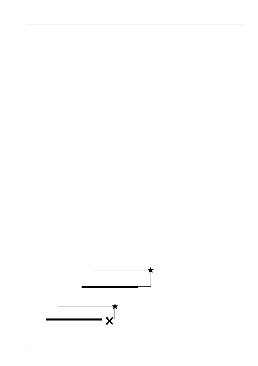
Code_Aster
®
Version
8.2
Titrate:
Operators
AFFE_CHAR_MECA
and
AFFE_CHAR_MECA_F
Date:
22/02/06
Author (S):
X. DESROCHES
Key
:
U4.44.01-I1
Page
:
41/92
Instruction manual
U4.4- booklet: Modeling
HT-62/06/004/A
4.21.11 Operands
SANS_NOEUD
/
SANS_GROUP_NO
/
SANS_NOEUD_QUAD
These operands make it possible to exclude from the nodes of the list of the nodes slaves, operation which is
recommended for nodes subjected to boundary conditions in the direction awaited of
contact (embedding example).
The operand
SANS_NOEUD_QUAD
(which is worth “NOT” by defect) allows to authorize or not the connection
linear realized automatically by the code in the case of quadratic meshs for the contact. This
operand is useful in the case of redundancy between these linear constraints and certain conditions
limits of the Dirichlet type. When the operand is worth “NOT”, although the nodes are excluded from the contact,
the nodes mediums of the quadratic meshs are always linearly related to the nodes, which can
to cause these interferences (null pivots). One can then use the option
SANS_NOEUD_QUAD=' OUI'
to solve this conflict.
4.21.12 Operands
DIST_MAIT
/
DIST_ESCL
These operands make it possible to take into account “holes” or “bumps” nonwith a grid, or
the thickness of the hulls (the relations of contact are written between two average surfaces) for
groups of meshs 1 (
DIST_MAIT
) or 2 (
DIST_ESCL
). One counts the distance positively in
the direction of the outgoing normal to the structure (cf document [R5.03.50 § 3.3]). Sizes
informed are either of the constants, or of the functions of the variables of space only.
4.21.13 Operand
VECT_NORM_ESCL
This operand allows the contact between two nodes in a direction
VECT_NORM_ESCL =
(vx, vy, vz)
data by the user. The contact is taken into account between meshs of the type
POI1
and
can be used only in the case of a nodal pairing. If this key word misses, the direction of
contact calculated at the time of the procedure of pairing is opposed to the normal Master.
4.21.14 Operand
NORMAL
This operand makes it possible to select a method of calculation of the normals according to the mesh Master
considered (by defect or explicitly by the control: NORMAL = “MAIT”) or according to one
average enters the meshs Masters and slaves with the control: NORMAL = “MAIT_ESCL”.
4.21.15
Operand
STOP_SINGULIER
This operand makes it possible to decontaminate the fatal error appearing if the matrix of contact is singular
by STOP_SINGULIER = “NOT”. One advises to use this operand only in 3D in the presence of
quadratic meshs whose nodes mediums are related to the nodes nodes.
4.21.16 Operand
TOLE_PROJ_EXT
Under certain conditions, Aster detects contact between two surfaces whereas there is not.
problem comes initially from an incorrect and imperfect definition of surfaces likely to enter in
contact. Let us take the case of the contact in 2D (surfaces of contact are thus segments).
Aster carries out a Re-projection on surface Master when a node slave is projected outwards
surface Master:
A solution consists in prohibiting this Re-projection:
slave
Master
slave
Master
Code_Aster
®
Version
8.2
Titrate:
Operators
AFFE_CHAR_MECA
and
AFFE_CHAR_MECA_F
Date:
22/02/06
Author (S):
X. DESROCHES
Key
:
U4.44.01-I1
Page
:
42/92
Instruction manual
U4.4- booklet: Modeling
HT-62/06/004/A
This solution does not take account of the borderline cases and can cause interpenetrations
inopportune if ever the mesh is not “optimal” (what is difficult to ensure within the framework
great transformations). One thus chose an intermediate solution by limiting the extension
surface Master at the time of the reprojection.
The limiting value of this Re-projection is fixed by the keyword “TOLE_PROJ_EXT” which takes for
argument the value (adimensional) of the extension da the mesh Master in which one authorizes
Re-projection. By defect, this value is fixed at 0.50. What means that any node slave
projecting with more than 50% on the right or on the left (in the case of a segment) the length of the mesh
Master will not be reprojeté. To prohibit Re-projection completely, it is enough to fix
TOLE_PROJ_EXT with zero. This operator is valid in 2D and 3D (in this last case, it acts of
extension of a surface mesh of contact).
4.21.17 Operand
TOLE_PROJ_INT
In certain cases, projection causes undesirable oscillations between two limiting situations
(mathematically, the unicity of the normal is not assured). There are then problems of
convergence, particularly when automatic geometrical reactualization is made
(REAC_GEOM=' AUTO'). The limiting value fixed by keyword “TOLE_PROJ_INT” makes it possible to regulate
finely the detection of projection on the internal geometrical entities. This adjustment is reserved
with the very pathological cases and exclusively when one uses surfaces of contact made up of
QUAD4.
4.21.18 Operand
ITER_MULT_MAXI
This operand makes it possible to fix the maximum number of iterations of contact/friction. The number
internal iterations maximum Nmax is fixed by the following relation:
Nmax = ITER_MULT_MAXI X Nesclaves
where Nesclaves is the number of nodes slaves of the couple of contact. By defect, ITER_MULT_MAXI
is fixed at 4, except for the method of the active stresses where the value is not modifiable and remains
fixed at two (value resulting from a theoretical result of convergence).
If one exceeds the maximum number of iterations of contact/friction, one obtains the error message
“Failure in the processing of the contact”. One can then try to refine the mesh, to subdivide the pitch of
time, or to change the value of ITER_MULT_MAXI.
slave
Master
Re-projection
(one is in the tolerance)
No Re-projection
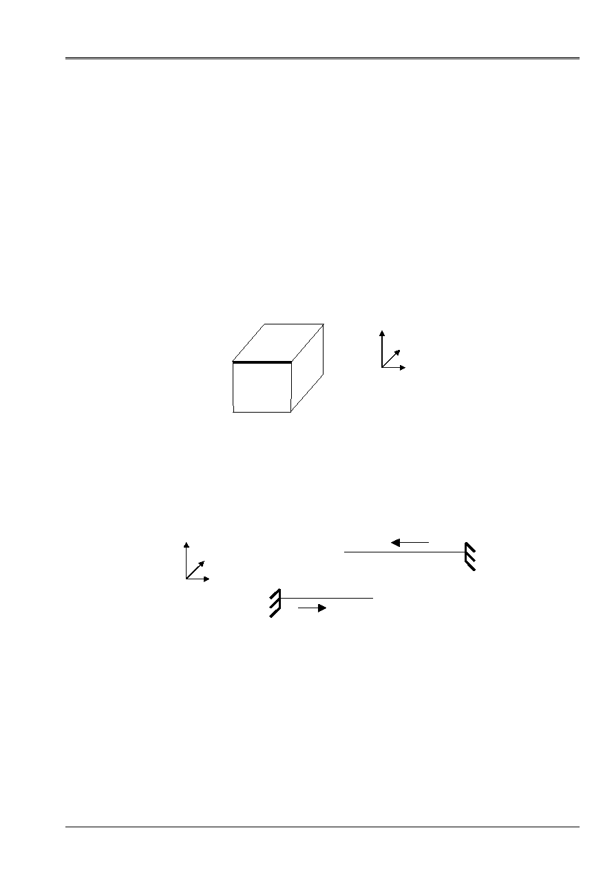
Code_Aster
®
Version
8.2
Titrate:
Operators
AFFE_CHAR_MECA
and
AFFE_CHAR_MECA_F
Date:
22/02/06
Author (S):
X. DESROCHES
Key
:
U4.44.01-I1
Page
:
43/92
Instruction manual
U4.4- booklet: Modeling
HT-62/06/004/A
4.21.19 Operands
VECT_Y and VECT_Z
For the discrete methods (LAGRANGIAN and PENALIZATION), operand VECT_Y has two
possible functions related to the contact with friction in 3D.
·
it makes it possible to define a local reference mark on the surface of an element, identifies on which one
break up the displacement of the slipping nodes. The construction of this local dihedral is
following: the first V1 vector is obtained by orthogonal projection of VECT_Y on
surface element considered, second V2 is obtained by vector product of V1 with
normal vector NR,
·
that is to say the block below whose face SB is locked according to y and face SF is subjected to
conditions of contact-friction. According to the line L can appear redundancies
between blockings and conditions of friction in direction Y. the problem is insoluble
(null pivots). One can raise these redundancies by informing VECT_Y to (0, 1, 0),
direction in which the redundancies appear. The problem can then be solved.
This type of difficulty appears only with METHOD = “LAGRANGIAN”.
Z
y
X
SF
SB
L
This operand allows also the modeling of the contact between coplanar beams in 3D:
·
Are 2 beams in the xOy plan. VECT_Y is the vector which, by vector product with
tangent vector with the beam, gives the normal to be used. That is to say:
VECT_Y^T = NR
Z
y
X
T1
T2
As here T1= (1,0,0) and T2= (- 1,0,0), with VECT_Y= (0,0,1), one obtains the normal
wished for each beam: N1= (0,1,0) and T2= (0, - 1,0). Attention with the fact that all this is
entirely related to the orientation of each beam.
For the method = “CONTINUES”, these keywords allow the user to exclude from the directions from
friction which is likely to enter in conflict with other boundary conditions of Dirichlet. They are used
thus in agreement with SANS_GROUP_NO and SANS_NOEUD. Excluded directions of friction
are indicated by VECT_Y (in 2D) and VECT_Y/VECT_Z (in 3D). The exclusion of the direction of
friction makes it possible nevertheless to keep the contacting character of a node.

Code_Aster
®
Version
8.2
Titrate:
Operators
AFFE_CHAR_MECA
and
AFFE_CHAR_MECA_F
Date:
22/02/06
Author (S):
X. DESROCHES
Key
:
U4.44.01-I1
Page
:
44/92
Instruction manual
U4.4- booklet: Modeling
HT-62/06/004/A
4.21.20 Operand
INTEGRATION/MODL_AXIS
The operand “INTEGRATION” makes it possible to select a method of integration numerical for
terms of contact and friction. Several methods are implemented; “NODE” for one
diagram of integration to the nodes, “GAUSS” for the conventional diagram of Gauss, “SIMPSON” for
diagram of Simpson (integration to the nodes and the mediums of the elements) and “DIMENSIONS” for one
adaptive diagram in the case of the linear/quadratic contact. The operand `
MODL_AXIS
`allows
to take into account the axisymmetric character of the problem. These operands are usable
only with the “CONTINUOUS” method.
4.21.21 Operand
FORMULATION
The operand
FORMULATION
allows to choose a formulation of the problem in displacement or in
speed. This choice relates to the whole of calculation. One uses it in dynamics (it does not have no direction in
statics). In dynamics, the advantage of the formulation of speed is to eliminate the oscillations
numerical speed and of the acceleration at the time of the impacts.
One uses this formulation with a diagram of a nature 1 of speed, available in
DYNA_NON_LINE
,
called TETA_METHODE. This diagram must be selected in the place of the diagram of Newmark or HHT. It
require a parameter TETA which takes its values between 0,5 and 1. TETA = 1 gives the maximum
of numerical damping usable only with the “CONTINUOUS” method.
4.21.22 Operand
ITER_CONT_MAXI/ITER_FROT_MAXI/ITER_GEOM_MAXI
These operands make it possible respectively to fix the maximum number of the iterations of contact, of
friction and geometrical. Let us recall that the geometrical loop is a loop which is used for
to reactualize pairing, the loop of friction is a fixed loop of point on the threshold of Coulomb
whereas the loop of contact is a loop of the type forced active which is used to determine them
effective surfaces of contact. These operands are usable only with the method
“CONTINUOUS”.
4.21.23 Operand
DIRECTION_APPA
This operand makes it possible to specify a direction of search for pairing. The search of
points likely to re-enter in contact is not founded any more on the principle of the proximity (the points them
closer) but according to the direction
DIRECTION_APPA = (vx, vy, vz)
data by the user.
In the case of them where pairing by direction is not possible (not main point in
direction given), one seeks the main point nearest in a close direction. This
operand is usable only with the “CONTINUOUS” method.
4.21.24 Operand COMPLIANCE
This operand makes it possible to activate the model of compliance for the “CONTINUOUS” method. This model
takes into account the aspect microscopic of surfaces (asperities) and allows a regularization of
model of contact of Signorini. Of dynamics, the contribution of this model consists of the possibility
to introduce a density of damping percussion which corresponds to the dissipation of the energy of
shock.
The law of compliance introduced into Code_Aster is a polynomial law (see Doc. [R5.03.52].
The three parameters of the law of compliance are ASPERITY, E_N and E_V.
ASPERITY
=/asperity,
[R]
E_N
=
/
e_n,
[R]
E_V
=
/
0.,
[DEFECT]
/
e_v, [R]

Code_Aster
®
Version
8.2
Titrate:
Operators
AFFE_CHAR_MECA
and
AFFE_CHAR_MECA_F
Date:
22/02/06
Author (S):
X. DESROCHES
Key
:
U4.44.01-I1
Page
:
45/92
Instruction manual
U4.4- booklet: Modeling
HT-62/06/004/A
4.21.25 Operands of resolution
These operands make it possible to select a method of calculation following the type of contact (2D/3D and
with or without friction) which one wants to treat.
METHOD
=
/
“FORCED”
[DEFECT]
/
“LAGRANGIAN”
/
“PENALIZATION”
/
“CONTINUES”
/
“VERIF”
This operand makes it possible to use the various methods of resolution.
STRESS
: By defect one deals with the problem of the exact unilateral contact without
friction with the method of the active stresses of [R5.03.50].
LAGRANGIAN
: The Lagrangian method makes it possible to treat in an exact way, by
multipliers of Lagrange, the problems of contact with or
without friction in 2D and 3D.
PENALIZATION
: The penalized method makes it possible to treat is:
- problems of contact penalized without friction 2D or 3D if
one informs
E_N
;
- problems of contact with friction in 2D or 3D with
a penalization on the terms of friction only if one
inform
E_T
and a penalization on the terms of contact and of
friction if one informs
E_T
and
E_N
.
CONTINUOUS
The method continues makes it possible to treat in an exact way, by
increased multipliers of Lagrange, the problems of
contact with or without friction in 2D and 3D. Coefficients
of increase (or regularization) are specified in
COEF_REGU_CONT and COEF_REGU_FROT (these coefficients are
strictly positive values.)
VERIF
The method of checking makes it possible to control if two surfaces
interpenetrate or not without imposing the conditions of contact.
It is thus a method which is worried only aspect
geometrical and which is inexpensive in terms of time CPU.
One can use it for example to control that the two lips
of a fissure do not interpenetrate.
Note:
The “CONTINUOUS” method is a modern and promising method. It is however very
recent in Code_Aster. Also advises one with the users rather to choose in a first
time one of the other methods and if required to test the method “CONTINUES” in one
the second time.
For the methods penalized and Lagrangian, one returns for more details to [R5.03.51].
FRICTION
=
/
“WITHOUT”
[DEFECT]
/
“COULOMB”
This operand makes it possible to activate the taking into account of a friction of Coulomb.
COULOMB
: value of the coefficient of friction for the criterion of Coulomb.
E_T
: coefficient of penalization on the slip for the method
penalized. It is not used and is not necessary when one
another method of resolution that
“PENALIZATION”
is active.
A value about the smallest Young modulus of the solids in
contact is initially recommended. The second calculation with
a value ten times larger east highly desirable to see

Code_Aster
®
Version
8.2
Titrate:
Operators
AFFE_CHAR_MECA
and
AFFE_CHAR_MECA_F
Date:
22/02/06
Author (S):
X. DESROCHES
Key
:
U4.44.01-I1
Page
:
46/92
Instruction manual
U4.4- booklet: Modeling
HT-62/06/004/A
sensitivity of the results compared to this coefficient. To increase
then the value of the coefficient until obtaining results
stable.
E_N
: coefficient of penalization on the interpenetration for the method
penalized. It is not used and is not necessary when one
another method of resolution that
“PENALIZATION”
is active.
A value about the smallest Young modulus of the solids in
contact is initially recommended. In practice the choice on
E_N
is broader than that on
E_T
and of great values are
usable (10
7
or 10
8
time the smallest Young modulus). One
increase the value of the coefficient until obtaining results
stable. Moreover it is possible to control the distances
of interpenetration and thus to refine its choice of coefficient, which
is not the case of the slip, since one does not know a priori
which are the slipping areas and not slipping whereas in
case of contact one can check that the distances
of interpenetration are not eccentric.
COEF_MATR_FROT
: coefficient, ranging between 0 and 1, of taking into account of the part
negative of geometrical rigidity. More this coefficient is large
better is convergence when one is close to balance and
more the resolution is difficult far from balance. A value of 0.5
thus is initially advised. The defect of 0 ensures
systematic convergence for a longer calculating time.
This coefficient is essential to treat contacts
surface with friction in 3D. It is not used the remainder of
time.
COEF_REGU_CONT
coefficient of increase for the method
“CONTINUES”
(Lagrangian increased) relating to the regularization of the laws of
contact. It can take values of about size of the pitch
time in dynamics (10
- 5
, 10
- 6
…) until much more
important (500 for example).
COEF_REGU_FROT
coefficient of increase for the method
“CONTINUES”
(Lagrangian increased) relating to the regularization of the laws of
friction.
SEUIL_INIT
initial threshold value of friction for the method
“CONTINUES”
(Lagrangian increased). It is by defect null what
corresponds to treat during the first iteration of threshold it
contact without friction.
4.21.26 Method VERIF
STOP_INTERP
=
/
“NOT”,
[DEFECT]
/
“YES”,
TOLE_INTERP
=/0.,
[DEFECT]
/
e_v, [R]
This method carries out a control of the interpenetration of two surfaces without imposing them
conditions of contact (if there is interpenetration, it will remain). If there is interpenetration, there will be one
ALARM. Parameter STOP_INTERP makes it possible to stop calculation instead of alarming the user.
TOLE_INTERP regulates the value of interpenetration.

Code_Aster
®
Version
8.2
Titrate:
Operators
AFFE_CHAR_MECA
and
AFFE_CHAR_MECA_F
Date:
22/02/06
Author (S):
X. DESROCHES
Key
:
U4.44.01-I1
Page
:
47/92
Instruction manual
U4.4- booklet: Modeling
HT-62/06/004/A
4.21.27 Method
SLIDE
SLIDE
=
/
“NOT”,
[DEFECT]
/
“YES”,
ALARME_JEU
/
0.0, [DEFECT]
/
alarm_jeu, [R]
This option is available only for the “FORCED” method and the method
“CONTINUOUS”.
It makes it possible to activate the mode of bilateral contact or out of slide, in which two surfaces
finding in contact remain “stuck” (i.e. with a null play) some is the evolution of
loading. It authorizes great relative slips and the slide mode is not activated
before surfaces are indeed in contact (it does not stick a priori two surfaces
distant of a play not no one if the loading does not imply it).
Operand “ALARME_JEU” makes it possible to activate an alarm as soon as the algorithm detects that, without
the method slide, there would be separation of two surfaces (a virtual play higher than zero). Its
value is regulated by defect with 0, which alarms the user as soon as surfaces would have
to take off without the activated option.
4.21.28 Operand
SMOOTHING
This operand makes it possible to smooth the normals on the surfaces of contact intervening in
calculation of the matrix of contact. One will note Q an unspecified node of surfaces of contact
(Master or slave), P a node of surface slave and M the main node obtained by
projection of the node P.
SMOOTHING
=
/“NOT”
[DEFECT]
For a pairing of the “master-slave” type the calculated normal is the normal entering to
the mesh containing Mr. For a pairing of the “nodal” type the calculated normal is
outgoing normal with the node slave P.
SMOOTHING
=
/“YES”
Smoothing is done in two stages:
·
the first stage of smoothing consists in carrying out an average of the normals with
meshs which contain the node Q,
·
the second stage consists in calculating an average of the normals at the tops of
net container Mr. This average being balanced by the functions of form
associated Mr.
Note:
For a pairing of the type
NODAL
smoothing does not bring any difference.
For a pairing of the type
MAIT_ESCL
smoothing has a behavior which varies according to
key word
NORMAL
.
NORMAL
=
/“MAIT”
The calculation of the matrix of contact is done according to the normal smoothed with the main node.
NORMAL
=
/“MAIT_ESCL”
The calculation of the matrix of contact is done according to the average of the normals smoothed with the node
slave and with the main node.

Code_Aster
®
Version
8.2
Titrate:
Operators
AFFE_CHAR_MECA
and
AFFE_CHAR_MECA_F
Date:
22/02/06
Author (S):
X. DESROCHES
Key
:
U4.44.01-I1
Page
:
48/92
Instruction manual
U4.4- booklet: Modeling
HT-62/06/004/A
4.21.29 Structure of data VALE_CONT
All the methods of contact with or without friction produce a structure of data of the type
VALE_CONT, which is a cham_no_s with the following components, in each node slave:
·
CONT: indicator of rubbing contact
- 0: no the contact
- 1: slipping contact
- 2: adherent contact
·
PLAY: value of the play
·
RN: normal reaction of contact normalizes
·
RNX: component according to DX of the normal reaction of contact
·
RNY: component according to DY of the normal reaction of contact
·
RNZ: component according to DZ of the normal reaction of contact
·
GLIX: component according to T
1
tangential slip (local reference mark)
·
GLIY: component according to T
2
tangential slip (local reference mark)
·
GLI: normalizes tangential slip
·
RTAX: component according to DX of the tangential force of adherence
·
RTAY: component according to DY of the tangential force of adherence
·
RTAZ: component according to DZ of the tangential force of adherence
·
RTGX: component according to DX of the tangential force of slip
·
RTGY: component according to DY of the tangential force of slip
·
RTGZ: component according to DZ of the tangential force of slip
·
X-ray: component according to DX of the force of rubbing contact (RNX+RTAX+RTGX)
·
RY: component according to DY of the force of rubbing contact (RNY+RTAY+RTGY)
·
RZ: component according to DZ of the force of rubbing contact (RNZ+RTAZ+RTGZ)
·
R: force of rubbing contact normalizes
It is printed as follows in the form of table:
MATABLE=POST_RELEVE_T (ACTION=_F (INTITULE=' INFOS FROTTMNT',
GROUP_NO=' ESCLAVE',
RESULTAT=U,
INST=10.,
TOUT_CMP=' OUI',
NOM_CHAM=' VALE_CONT',
OPERATION=' EXTRACTION',),);
IMPR_TABLE (TABLE=MATABLE);

Code_Aster
®
Version
8.2
Titrate:
Operators
AFFE_CHAR_MECA
and
AFFE_CHAR_MECA_F
Date:
22/02/06
Author (S):
X. DESROCHES
Key
:
U4.44.01-I1
Page
:
49/92
Instruction manual
U4.4- booklet: Modeling
HT-62/06/004/A
4.22 Key word
FORCE_NODALE
4.22.1 Drank
Key word factor usable to apply, with nodes or groups of nodes, nodal forces,
defined component by component in the reference mark
TOTAL
or in an oblique reference mark defined by
three nautical angles.
According to the name of the operator called, the values are provided directly (
AFFE_CHAR_MECA
) or
via a concept
function
(
AFFE_CHAR_MECA_F)
.
4.22.2 Syntax
·
for
AFFE_CHAR_MECA
FORCE_NODALE=_F
(
|
NODE =
lno,
[l_noeud]
|
GROUP_NO
= lgno,
[l_gr_noeud]
|
FX=
fx
,
[R]
|
FY=
fy
,
[R]
|
FZ=
fz
,
[R]
|
MX=
MX
,
[R]
|
MY=
my
,
[R]
|
MZ=
mz
,
[R]
ANGL_NAUT
= (
,
,
),
[l_R]
),
·
for
AFFE_CHAR_MECA_F
FORCE_NODALE=_F
(
|
NODE =
lno,
[l_noeud]
|
GROUP_NO
= lgno,
[l_gr_noeud]
|
FX=
fxf
,
[function]
|
FY=
fyf
,
[function]
|
FZ=
fzf
,
[function]
|
MX=
mxf
,
[function]
|
MY=
myf
,
[function]
|
MZ=
mzf
,
[function]
ANGL_NAUT
= (
_f,
_f,
_f
)
,
[l_fonction]
),
4.22.3 Operands
fx, fy, fz, MX, my, mz
or
fxf, fyf, fzf, mxf, myf, mzf
Values of the components of the nodal forces applied to the specified nodes. These forces
nodal will come to superimpose itself on the nodal forces resulting, possibly, others
loadings. Into axisymmetric, the values correspond to a sector of 1 radian (to divide it
real loading by 2
).
(
,)
or
(
_f, _f, _f,)
List of the 3 angles, in degrees, which define the oblique reference mark of application of the nodal forces
(the last angles of the list can be omitted if they are null). The nautical angles allow
to pass from the total reference mark of definition of the co-ordinates of the mesh to an oblique reference mark
unspecified (see operator
AFFE_CARA_ELEM
[U4.42.01]). By defect the angles are
identically null and thus the components of forces are defined in the reference mark
TOTAL
.

Code_Aster
®
Version
8.2
Titrate:
Operators
AFFE_CHAR_MECA
and
AFFE_CHAR_MECA_F
Date:
22/02/06
Author (S):
X. DESROCHES
Key
:
U4.44.01-I1
Page
:
50/92
Instruction manual
U4.4- booklet: Modeling
HT-62/06/004/A
4.23 Key word
LIAISON_SOLIDE
4.23.1 Drank
Key word factor allowing to modelize an indeformable part of a structure.
One imposes linear relations between the degrees of freedom of the nodes of this indeformable part
so that relative displacements between these nodes are null.
These nodes are defined by the groups of meshs, the meshs, the groups of nodes or the list of
nodes to which they belong.
4.23.2 Syntax
·
for
AFFE_CHAR_MECA
and
AFFE_CHAR_MECA_F
LIAISON_SOLIDE
=_F
(
/MESH
= lma
,
[l_maille]
/
GROUP_MA
=
lgma,
[l_gr_maille]
/
NODE
=
lno
,
[l_noeud]
/
GROUP_NO
=
lgno,
[l_gr_noeud]
NUME_LAGR
=/“NORMAL”,
[DEFECT]
/
“AFTER”
,
),
NUME_LAGR:
·
If
“NORMAL”
, the two multipliers of Lagrange associated with the relation will be such as
first will be located before all the terms implied in the relation and the second after, in
the assembled matrix.
·
If
“AFTER”
, the two multipliers of Lagrange associated with the relation will be located afterwards
all terms implied in the relation, the assembled matrix.
This choice has the advantage of having an assembled matrix whose overall dimension is more
weak but has the disadvantage to be able to reveal a singularity in the matrix.
Note:
In a general way, one imposes:
·
in 2D (nb_ddl * nb_noeud3) relations
·
in 3D (nb_ddl * nb_noeud6) relations
where
·
nb_ddl is the number of degrees of freedom per node,
·
nb_noeud is the number of nodes of the list given afterwards
LIAISON_SOLIDE
since a solid is determined by the position of one of its points and a reference mark in it
not.
Relations are written by taking the vectorial formula translating a movement of
rigid body in small rotations:
where
is an arbitrary node of the solid.

Code_Aster
®
Version
8.2
Titrate:
Operators
AFFE_CHAR_MECA
and
AFFE_CHAR_MECA_F
Date:
22/02/06
Author (S):
X. DESROCHES
Key
:
U4.44.01-I1
Page
:
51/92
Instruction manual
U4.4- booklet: Modeling
HT-62/06/004/A
4.24 Key word
LIAISON_ELEM
4.24.1 Drank
While calling “left massive” a piece of structure modelized with isoparametric elements
3D, this key word factor makes it possible to modelize the connection:
·
of a massive part with a part beam [R3.03.03] or a pipe section [R3.08.06],
·
of a hull part with a part beam [R3.06.03] or a pipe section [R3.08.06].
The goal of this functionality is not to account for the scales length between the parts to
to connect but to allow a simplification of modeling by replacing a massive part
by a beam part for example.
The connection is treated by imposing linear relations between the degrees of freedom of the nodes of
junction of the two parts to be connected, without imposing superfluous relations.
4.24.2 Syntax (AFFE_CHAR_MECA only)
LIAISON_ELEM
=_F
(
/
OPTION
=
/
“3d_POU”,
/
“COQ_POU”,
AXE_POUTRE=
(X, y, Z), [l_R]
CARA_ELEM
= will cara, [cara_elem]
/
OPTION
=
“3d_TUYAU”,
AXE_POUTRE= (X, y, Z), [l_R]
CARA_ELEM
= will cara, [cara_elem]
/
OPTION
=
“COQ_TUYAU”,
AXE_POUTRE= (X, y, Z), [l_R]
CARA_ELEM
= will cara, [cara_elem]
/MAILLE_1 = lma1, [l_maille]
/
GROUP_MA_1 =
lgma1,
[l_gr_maille]
/NOEUD_2 = lno2, [l_noeud]
/
GROUP_NO_2 =
lgno2,
[l_gr_noeud]
NUME_LAGR
=/“NORMAL”,
[DEFECT]
/
“AFTER”
,
ANGL_MAX =/1.,
[DEFECT]
/
Eng,
[R]
),
4.24.3 Operands of the option
“3d_POU”
OPTION = “3d_POU”
This option makes it possible to connect a massive part 3D with a part modelized with
beams of Euler or Timoshenko.
/MAILLE_1 =
/
GROUP_MA_1
=
These operands define the surface meshs of the massive part modelizing
trace section of the beam on this massive part. These meshs must have been
affected by finite elements of faces of elements 3D before.
/NOEUD_2 =
/
GROUP_NO_2
=
These operands define the node of the beam to be connected to the massive part. Thus if
one uses
NOEUD_2
, one should give one node and if one uses
GROUP_NO_2
,
one should give one group, the aforementioned containing one node.

Code_Aster
®
Version
8.2
Titrate:
Operators
AFFE_CHAR_MECA
and
AFFE_CHAR_MECA_F
Date:
22/02/06
Author (S):
X. DESROCHES
Key
:
U4.44.01-I1
Page
:
52/92
Instruction manual
U4.4- booklet: Modeling
HT-62/06/004/A
Precaution for use:
The massive part must be with a grid with quadratic elements because the coefficients
relations to be imposed are numerically integrated geometrical quantities. For
that these integrals are evaluated correctly, it is necessary to have elements
quadratic.
Note:
A connection between a massive part 3D and a beam part requires six relations
linear.
4.24.4 Operands of the option
“COQ_POU”
This option makes it possible to connect a part with a grid in hull with a beam part.
AXE_POUTRE
=
Allows to define the axis of the beam to be connected, whose end is
lno2
or
lgno2
(1 only
node).
CARA_ELEM = will cara
Concept created by the control
AFFE_CARA_ELEM
, containing the geometrical characteristics
hull.
/MAILLE_1 =
/
GROUP_MA_1
=
These operands define the meshs of edge of the part with a grid in hulls (the meshs of edge
are thus
SEG2
or
SEG3
according to selected modeling). These meshs must have been
affected by finite elements of edge of hulls before.
/NOEUD_2 =
/
GROUP_NO_2
=
These operands define the node of the beam to be connected to the hull part. Thus if one uses
NOEUD_2
one should give one node, and if one uses
GROUP_NO_2
, one should not give
that only one group, the aforementioned containing one node.
Precaution for use:
The trace of the section of the beam on the hull part must correspond exactly to the meshs
of edge defined by
MAILLE_1
or
GROUP_MA_1
. This implies the identity of the centers of inertia, of
surfaces of the sections hull and beam in opposite.
4.24.5 Operands of the option “3d_TUYAU”
OPTION = “3d_TUYAU”,
This option makes it possible to connect a massive part 3D with a part modelized with
elements PIPE.
AXE_POUTRE
=
Defines the axis of the pipe to connect, whose end is only one node (lno2 or lgno2).
CARA_ELEM = will cara
Idem [§4.19.4].
/MAILLE_1
=
/
GROUP_MA_1
=
These operands define the surface meshs of the massive part modelizing the trace of
the section of the pipe on this massive part. These meshs must be affected by
finite elements of faces of elements 3D before.
/NOEUD_2
=
/
GROUP_NO_2
=
These operands define the node of the pipe to be connected to the massive part.

Code_Aster
®
Version
8.2
Titrate:
Operators
AFFE_CHAR_MECA
and
AFFE_CHAR_MECA_F
Date:
22/02/06
Author (S):
X. DESROCHES
Key
:
U4.44.01-I1
Page
:
53/92
Instruction manual
U4.4- booklet: Modeling
HT-62/06/004/A
Note:
A connection between a massive part 3D and a pipe part requires six relations
linear for the degrees of freedom of beam, plus a relation on the mode of
swelling, plus twelve relations corresponding to the transmission of the modes of Fourier
two and three of ovalization of the pipe.
4.24.6 Operands of option “COQ_TUYAU”
OPTION = “COQ_TUYAU”
This option makes it possible to connect a part with a grid in hull to a part with a grid with
elements pipe.
AXE_POUTRE
=
Allows to define the axis of the pipe to be connected, whose end is lno2 or lgno2 (only one node).
CARA_ELEM = will cara,
Concept created by control AFFE_CARA_ELEM, containing the geometrical characteristics
hull.
/MAILLE_1
=
/
GROUP_MA_1
=
These operands define the meshs of edge of the part with a grid in hulls (the meshs of
edge are thus SEG2 or SEG3 following selected modeling). These meshs must have
summer affected by finite elements of edge of hulls before.
/NOEUD_2
=
/
GROUP_NO_2
=
These operands define the node of the pipe to be connected to the hull part. Thus if one
use NOEUD_2 one must give one node, and if GROUP_NO_2 is used, one does not have
to give that only one group, the aforementioned containing one node.
Precaution for use:
The trace of the section of the pipe on the hull part must correspond exactly to
meshs of edge defined by MAILLE_1 or GROUP_MA_1. This implies the identity of
, surface centers of inertia of the sections hull and pipe in opposite. Consequently
connections of the type “pricking” are impossible.
Note:
A connection between a hull part and a pipe part requires the same relations
linear that option “COQ_POU” on the ddl of beam of the element pipe in addition to
relations on the ddl of ovalization, roll and swelling.
4.24.7 Operand ANGL_MAX
ANGL_MAX
=/1.
, [DEFECT]
/
Eng,
[R]
Angle (in degree) allowing to check if the meshs of the lists lma1 or lgma1 have normals
forming an angle higher than Eng between them. If it is the case, there is emission of a message
of alarm.
The programming is made only in the case 3D (thus “3d_TUYAU” and “3d_POU”).

Code_Aster
®
Version
8.2
Titrate:
Operators
AFFE_CHAR_MECA
and
AFFE_CHAR_MECA_F
Date:
22/02/06
Author (S):
X. DESROCHES
Key
:
U4.44.01-I1
Page
:
54/92
Instruction manual
U4.4- booklet: Modeling
HT-62/06/004/A
4.24.8 Operand
NUME_LAGR
·
If
“NORMAL”
, the two multipliers of Lagrange associated with the relation will be such as
first will be located before all the terms implied in the relation and the second after, in
the assembled matrix.
·
If
“AFTER”
, the two multipliers of Lagrange associated with the relation will be located afterwards
all terms implied in the relation, the assembled matrix.
This choice has the advantage of having an assembled matrix whose overall dimension is more
weak but has the disadvantage to be able to reveal a singularity in the matrix.
4.25 Key word
LIAISON_UNIF
4.25.1 Drank
Key word factor allowing to impose the same value (unknown) on degrees of freedom of one
together of nodes.
These nodes are defined by the groups of meshs, the meshs, the groups of nodes or the list of
nodes to which they belong.
4.25.2 Syntax
·
for
AFFE_CHAR_MECA
and
AFFE_CHAR_MECA_F
LIAISON_UNIF
=_F
(
/MESH
= lma
,
[l_maille]
/
GROUP_MA
=
lgma,
[l_gr_maille]
/
NODE
=
lno
,
[l_noeud]
/
GROUP_NO
=
lgno,
[l_gr_noeud]
DDL
=
|
“DX”,
|
“DY”,
|
“DZ”,
|
“DRX”,
|
“DRY”,
|
“DRZ”,
)
4.25.3 Operand
/MESH
/
GROUP_MA
/
NODE
/
GROUP_NO
These operands make it possible to define a list of nodes
from which one eliminated them
redundancies, (for
NET
and
GROUP_MA
, they are connectivities of the meshs).
DDL
This operand makes it possible to define a list of degrees of freedom
texts
taken among:
“DX”, “DY”, “DZ”, “DRX”, “DRY”, “DRZ”
conditions resulting kinematics are:
for

Code_Aster
®
Version
8.2
Titrate:
Operators
AFFE_CHAR_MECA
and
AFFE_CHAR_MECA_F
Date:
22/02/06
Author (S):
X. DESROCHES
Key
:
U4.44.01-I1
Page
:
55/92
Instruction manual
U4.4- booklet: Modeling
HT-62/06/004/A
4.26 Key word
LIAISON_CHAMNO
4.26.1 Drank
Key word factor usable to define a linear relation between all ddls present in a concept
CHAM_NO
. This key word can be also used to impose on the structure (or a part) a work
given, for a loading calculated as a preliminary with another AFFE_CHAR_MECA and leading to one
assembled vector produces by ASSE_VECTEUR [U4.61.23].
4.26.2 Syntax (AFFE_CHAR_MECA only)
LIAISON_CHAMNO=_F (
CHAM_NO =
chamno,
[cham_no]
COEF_IMPO =
,
[R]
NUME_LAGR
=
/
“NORMAL”,
[DEFECT]
/
“AFTER”
,
)
4.26.3 Operands
CHAM_NO =
Name of
cham_no
who is used to define the linear relation. The ddls connected are all those present in
chamno
. The coefficients to be applied to the ddls are the values of
chamno
for these ddls.
Example:
Let us suppose that one has one
chamno
relating to two nodes of name N01 and N02 respectively
carriers of the ddls
“DX”
,
“DY”
and
“DZ”
for the N01 node and
“DX”
,
“DY”
,
“DZ”
,
“DRX”
,
“DRY”
and
“DRZ”
for the N02 node.
Also let us suppose that it
chamno
has the following values for these ddls:
2.
“DX” N01
1.
“DY” N01
3.
“DZ” N01
1.
“DX” N02
4.
“DY” N02
2.
“DZ” N02
3.
“DRX”
N02
5.
“DRY”
N02
2.
“DRZ”
N02
The linear relation that one will impose is:
2.* DX (N01) +1.* DY (N01) +3.* DZ (N01)
+ 1.* DX (N02) +4.* DY (N02) +2.* DZ (N02)
+ 3.* DRX (N02) +5.* DRY (N02) +2.* DRZ (N02) =
COEF_IMPO =
It is the value of the real coefficient
with the second member of the linear relation.
NUME_LAGR =
·
if
“NORMAL”
, the two multipliers of Lagrange associated with the relation will be such as
first will be located before all the terms implied in the relation and the second after, in
the assembled matrix,
·
if
“AFTER”
, the two multipliers of Lagrange associated with the relation will be located afterwards
all terms implied in the relation, the assembled matrix.
This choice has the advantage of having an assembled matrix whose overall dimension is more
weak but has the disadvantage to be able to reveal a singularity in the matrix.

Code_Aster
®
Version
8.2
Titrate:
Operators
AFFE_CHAR_MECA
and
AFFE_CHAR_MECA_F
Date:
22/02/06
Author (S):
X. DESROCHES
Key
:
U4.44.01-I1
Page
:
56/92
Instruction manual
U4.4- booklet: Modeling
HT-62/06/004/A
4.27 Key word
VECT_ASSE
4.27.1 Drank
Key word allowing to assign a second member in the form of one
CHAM_NO
in the controls
STAT_NON_LINE
and
DYNA_NON_LINE
. It
CHAM_NO
is transmitted to these controls via the name of
loading.
4.27.2 Syntax
VECT_ASSE
=
chamno
[cham_no_DEPL_R]
4.27.3 Operand
VECT_ASSE
chamno
is the name of
CHAM_NO
who will serve as second member in the controls
STAT_NON_LINE
or
DYNA_NON_LINE
.
The mode of use can see itself in the following way:
tank = AFFE_CHAR_MECA (
MODEL
=
model,
VECT_ASSE
=
chamno,
);
resu = STAT_NON_LINE
(
MODEL
=
model,
EXCIT
=
_F
(LOAD
=
tank),
…
)
;
4.28 Key word
FORCE_FACE
4.28.1 Drank
Key word factor usable to apply surface forces to a face (of voluminal element)
defined by one or more meshs or of the groups of meshs of the triangle type or quadrangle.
According to the name of the operator called, the values are provided directly (
AFFE_CHAR_MECA
) or
via a concept
function
(
AFFE_CHAR_MECA_F)
.
4.28.2 Syntax
·
for
AFFE_CHAR_MECA
FORCE_FACE=_F
(
|
NET =
lma, [l_maille]
|
GROUP_MA=
lgma,
[l_gr_maille]
|
FX=
fx
,
[R]
|
FY=
fy
,
[R]
|
FZ=
fz
,
[R]
)
·
for
AFFE_CHAR_MECA_F
FORCE_FACE=_F
(
|
NET =
lma, [l_maille]
|
GROUP_MA=
lgma,
[l_gr_maille]
|
FX=
fxf
, [function]
|
FY=
fyf
, [function]
|
FZ=
fzf
, [function]
)
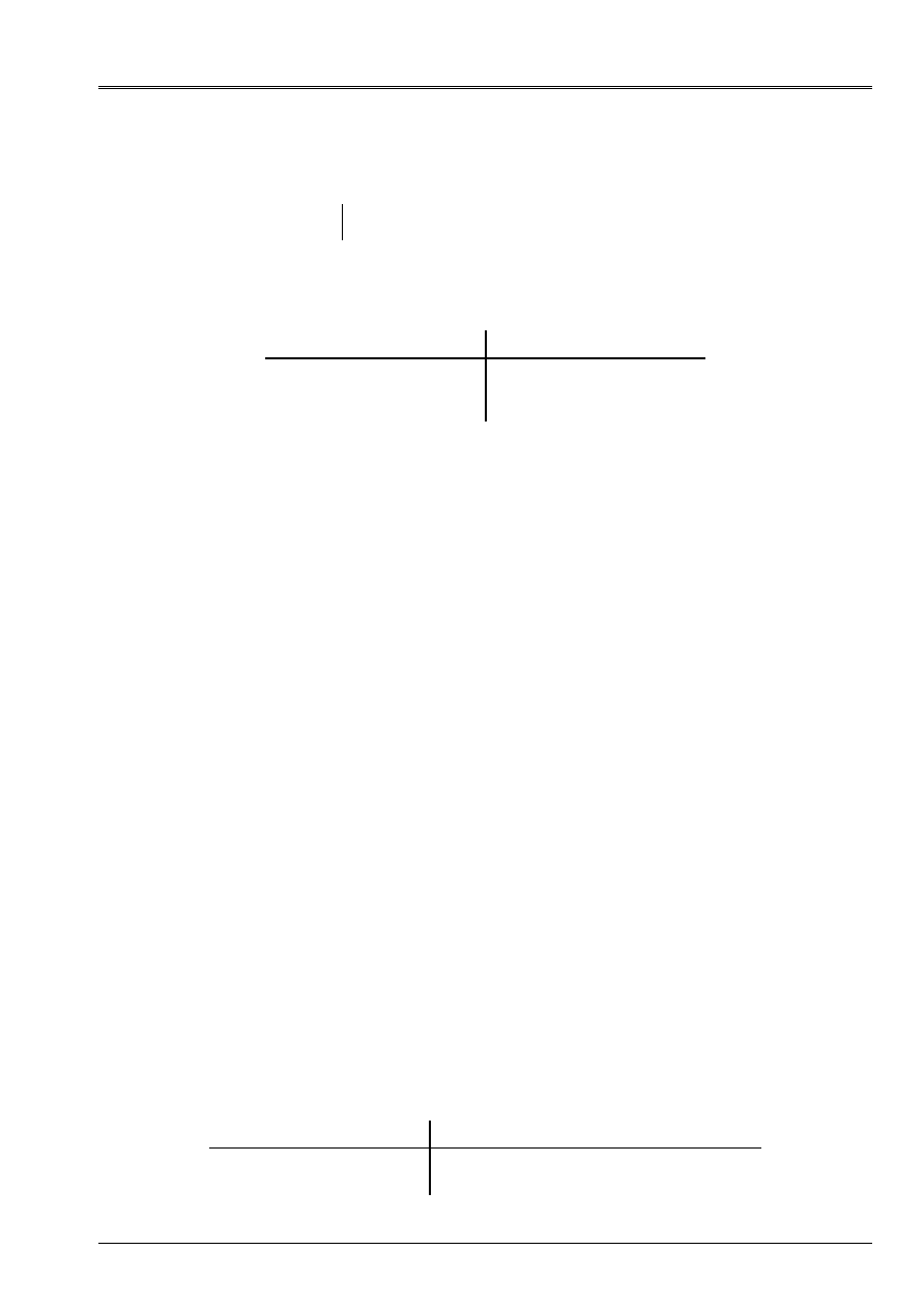
Code_Aster
®
Version
8.2
Titrate:
Operators
AFFE_CHAR_MECA
and
AFFE_CHAR_MECA_F
Date:
22/02/06
Author (S):
X. DESROCHES
Key
:
U4.44.01-I1
Page
:
57/92
Instruction manual
U4.4- booklet: Modeling
HT-62/06/004/A
4.28.3 Operands
fx, fy, fz
fxf, fyf, fzf
values of the components in the reference mark
TOTAL
forces
surface applied to the face.
4.28.4 Modelings and meshs
This loading applies to the types of meshs and following modelings:
Net Modélisation
TRIA3, TRIA6,
QUAD4, QUAD8, QUAD9,
QUAD8, TRIA6
3D, 3d_SI, 3d_INCO
3d_HHMD, 3d_HMD,
3d_THHD, 3d_THHMD,
3d_THMD
4.29 Key word
FORCE_ARETE
4.29.1 Drank
Key word factor usable to apply linear forces, with an edge of voluminal element or of
hull. This edge is defined by one or more meshs or of the groups of meshs of the type
segment.
According to the name of the operator called, the values are provided directly (
AFFE_CHAR_MECA
) or
via a concept
function
(
AFFE_CHAR_MECA_F)
.
4.29.2 Syntax
·
for
AFFE_CHAR_MECA
FORCE_ARETE
=_F
(
|
NET =
lma,
[l_maille]
|
GROUP_MA=
lgma,
[l_gr_maille]
|
FX=
fx
,
[R]
|
FY=
fy
,
[R]
|
FZ=
fz
,
[R]
|
MX=
MX
,
[R]
|
MY=
my
,
[R]
|
MZ=
mz
,
[R]
)
·
for
AFFE_CHAR_MECA_F
FORCE_ARETE
=_F
(
|
NET =
lma,
[l_maille]
|
GROUP_MA=
lgma,
[l_gr_maille]
|
FX=
fxf
,
[function]
|
FY=
fyf
,
[function]
|
FZ=
fzf
,
[function]
|
MX=
mxf
,
[function]
|
MY=
myf
,
[function]
|
MZ=
mzf
,
[function]
)
4.29.3 Operands
fx, fy, fz, MX, my, mz
fxf, fyf, fzf, mxf, myf, mzf
: values of the components in the reference mark
TOTAL
linear forces applied to the edge.
4.29.4 Modelings and meshs
This loading applies to the types of meshs and following modelings:
Net Modélisation
SEG2
SEG2, SEG3
DKT, DST, Q4G
3D, 3d_SI, 3d_INCO
COQUE_3D
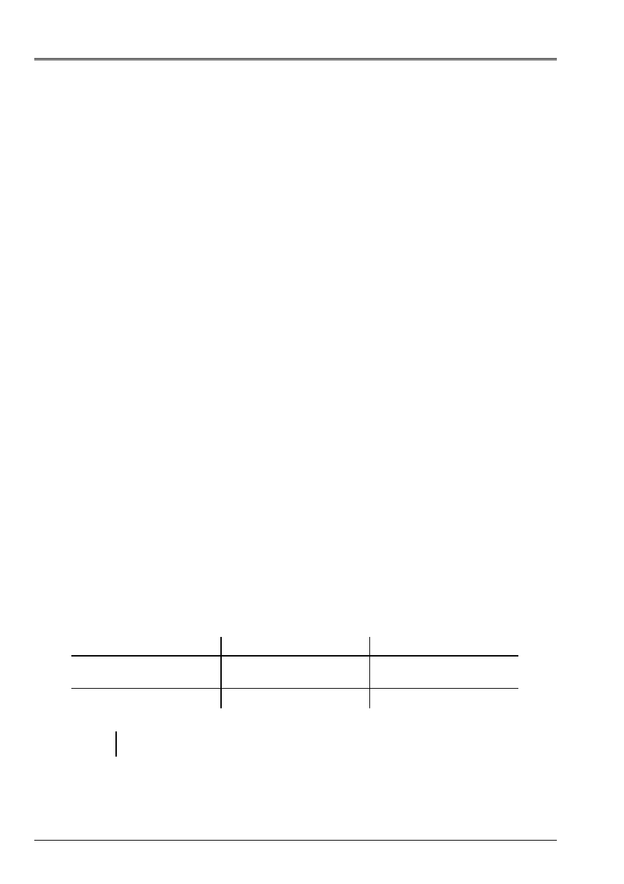
Code_Aster
®
Version
8.2
Titrate:
Operators
AFFE_CHAR_MECA
and
AFFE_CHAR_MECA_F
Date:
22/02/06
Author (S):
X. DESROCHES
Key
:
U4.44.01-I1
Page
:
58/92
Instruction manual
U4.4- booklet: Modeling
HT-62/06/004/A
4.30 Key word
FORCE_CONTOUR
4.30.1 Drank
Key word factor usable to apply linear forces, at the edge of a field (
2D
, AXIS or
AXIS_FOURIER
) defined by one or more meshs or of the groups of meshs.
According to the name of the operator called, the values are provided directly (
AFFE_CHAR_MECA
) or
via a concept
function
(
AFFE_CHAR_MECA_F)
.
4.30.2 Syntax
·
for
AFFE_CHAR_MECA
FORCE_CONTOUR=_F
(
|
NET =
lma,
[l_maille]
|
GROUP_MA=
lgma,
[l_gr_maille]
|
FX=
fx
,
[R]
|
FY=
fy
,
[R]
|
FZ=
fz
,
[R]
|
MX=
MX
,
[R]
|
MY=
my
,
[R]
|
MZ=
mz
,
[R]
)
·
for
AFFE_CHAR_MECA_F
FORCE_CONTOUR=_F
(
|
NET =
lma,
[l_maille]
|
GROUP_MA=
lgma,
[l_gr_maille]
|
FX=
fxf
,
[function]
|
FY=
fyf
,
[function]
|
FZ=
fzf
,
[function]
|
MX=
mxf
,
[function]
|
MY=
myf
,
[function]
|
MZ=
mzf
,
[function]
)
4.30.3 Operands
fx, fy, fz, MX,
my, mz
fxf, fyf, fzf,
mxf, myf, mzf
values of the components in the reference mark
TOTAL
linear forces
applied to contour.
4.30.4 Modelings and meshs
This loading applies to the types of meshs and following modelings:
Net Modélisation
Component
SEG2, SEG3
C_PLAN
D_PLAN
AXIS
Fx, Fy
Fx, Fy
Fx, Fy
SEG2, SEG3
AXIS_FOURIER
Fx (R), Fy (Z), Fz (
)
Note:
In plan, the forces are to be provided per unit of length of the mesh, into axisymmetric, them
forces required are brought back to a sector of 1 radian (to divide the real loading by 2
).
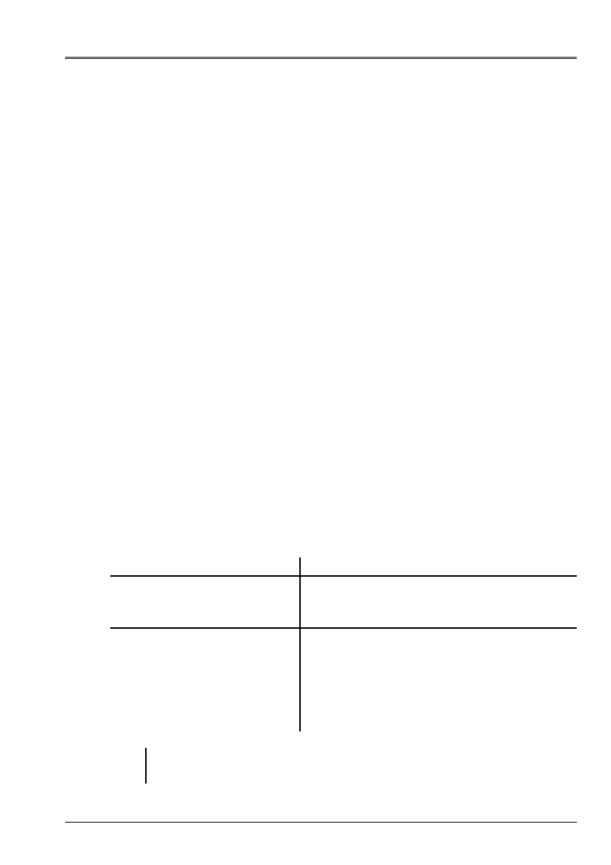
Code_Aster
®
Version
8.2
Titrate:
Operators
AFFE_CHAR_MECA
and
AFFE_CHAR_MECA_F
Date:
22/02/06
Author (S):
X. DESROCHES
Key
:
U4.44.01-I1
Page
:
59/92
Instruction manual
U4.4- booklet: Modeling
HT-62/06/004/A
4.31 Key word
FORCE_INTERN
4.31.1 Drank
Key word factor usable to apply voluminal forces (2D or 3D), with a field defined by
one or more meshs or of the groups of meshs of the voluminal type.
According to the name of the operator called, the values are provided directly (
AFFE_CHAR_MECA
) or
via a concept
function
(
AFFE_CHAR_MECA_F)
.
4.31.2 Syntax
·
for
AFFE_CHAR_MECA
FORCE_INTERN=_F
(
/ALL =
“YES”,
/
|
NET =
lma,
[l_maille]
|
GROUP_MA
= lgma,
[l_gr_maille]
|
FX=
fx
,
[R]
|
FY=
fy
,
[R]
|
FZ=
fz
,
[R]
)
·
for
AFFE_CHAR_MECA_F
FORCE_INTERN=_F
(
/ALL =
“YES”,
/
|
NET =
lma,
[l_maille]
|
GROUP_MA
= lgma,
[l_gr_maille]
|
FX=
fxf
,
[function]
|
FY=
fyf
,
[function]
|
FZ=
fzf
,
[function]
)
4.31.3 Operands
fx, fy, fz,
fxf, fyf, fzf
:
values of the components in the reference mark
TOTAL
forces
voluminal applied to the field.
4.31.4 Modelings and meshs
This loading applies to the types of meshs and following modelings:
Net Modélisation
HEXA8, HEXA20, HEXA27
PENTA6, PENTA15
TETRA4, TETRA10
PYRAM5, PYRAM13
3D, 3d_SI, 3d_INCO
3d_HHMD, 3d_HMD, 3d_THHD, 3d_THHMD,
3d_THMD, 3d_THHM, 3d_THM, 3d_HM, 3d_THH,
3d_HHM
TRIA3, TRIA6,
QUAD4, QUAD8, QUAD9
C_PLAN
D_PLAN
AXIS
AXIS_FOURIER
AXIS_SI
AXIS_INCO
AXIS_THHM, AXIS_HM, AXIS_THH, AXIS_HHM,
AXIS_THM
D_PLAN_THHM, D_PLAN_HM, D_PLAN_THH,
D_PLAN_HHM, D_PLAN_THM
Note:
In 2D (resp 3D), the forces are to be provided per unit of area (resp volume), in
axisymmetric, the forces required are brought back to a sector of 1 radian (to divide it
real loading by 2
).
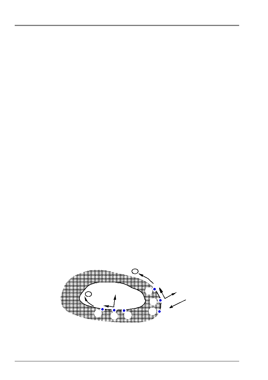
Code_Aster
®
Version
8.2
Titrate:
Operators
AFFE_CHAR_MECA
and
AFFE_CHAR_MECA_F
Date:
22/02/06
Author (S):
X. DESROCHES
Key
:
U4.44.01-I1
Page
:
60/92
Instruction manual
U4.4- booklet: Modeling
HT-62/06/004/A
4.32 Key word
PRES_REP
4.32.1 Drank
Key word factor usable to apply a pressure to a field of continuous medium 2D or 3D.
According to the name of the operator called, the values are provided directly (
AFFE_CHAR_MECA
) or
via a concept
function
(
AFFE_CHAR_MECA_F)
.
4.32.2 Syntax
·
for
AFFE_CHAR_MECA
|
PRES_REP=_F
(
/ALL =
“YES”,
/
|
NET =
lma, [l_maille]
|
GROUP_MA
= lgma,
[l_gr_maille]
|
CLOSE =
P,
[R]
|
CISA_2D =
T,
[R]
)
·
for
AFFE_CHAR_MECA_F
|
PRES_REP=_F
(
/ALL =
“YES”,
/
|
NET =
lma, [l_maille]
|
GROUP_MA
= lgma,
[l_gr_maille]
|
CLOSE =
PF,
[function]
|
CISA_2D =
Tf,
[function]
)
4.32.3 Operands
| CLOSE = P (PF)
Value of the imposed pressure
P
(or
PF
) is positive according to the contrary direction of the normal to the element: that is to say
the tensor
stresses, the imposed loading is:
.
| CISA_2D = T (Tf)
Value of imposed shearing
T
(or
Tf
) is positive according to the tangent with the element.
For the definition of the normals and tangents, one will refer to the definitions given to [§4.1].
Example:
+
3
1
2
2
3
T
N
T
N
+
1
p > 0
- pn
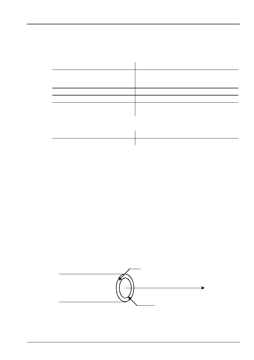
Code_Aster
®
Version
8.2
Titrate:
Operators
AFFE_CHAR_MECA
and
AFFE_CHAR_MECA_F
Date:
22/02/06
Author (S):
X. DESROCHES
Key
:
U4.44.01-I1
Page
:
61/92
Instruction manual
U4.4- booklet: Modeling
HT-62/06/004/A
4.32.4 Modelings and meshs
The loading of pressure applies to the types of meshs and following modelings:
Type of Mesh
Modeling
SEG2 SEG3
AXIS, D_PLAN, C_PLAN, AXIS_FOURIER
D PLAN HHM, D PLAN HM, D PLAN THHM,
D_PLAN_THM
SEG3
AXIS_HHM, AXIS_HM, AXIS_THHM, AXIS_THM
TRIA6 QUAD8
3d_HHM, 3d_HM, 3d_THHM, 3d_THM
TRIA3, QUAD4
TRIA6, QUAD8, QUAD9
3D
The loading of shearing applies to the meshs and following modelings:
Type of Mesh
Modeling
SEG2 SEG3
AXIS, D_PLAN, C_PLAN, AXIS_FOURIER
4.33 Key word
EFFE_FOND
Key word factor usable to calculate the basic effect on a branch of piping (modeling 3D
exclusively) subjected to a pressure P. interns.
4.33.1 Syntax
·
for
AFFE_CHAR_MECA
|
EFFE_FOND
=_F
(
|
NET =
lma,
[l_maille]
|
GROUP_MA=
lgma,
[l_gr_maille]
GROUP_MA_INT
=
gtrou,
[l_gr_maille]
CLOSE =
p,
[R]
)
·
for
AFFE_CHAR_MECA_F
|
EFFE_FOND
=_F
(
|
NET =
lma,
[l_maille]
|
GROUP_MA=
lgma,
[l_gr_maille]
GROUP_MA_INT
=
gtrou,
[l_gr_maille]
CLOSE =
PF,
[function]
)
4.33.2 Operands
Group of mesh:
gmat
Group of mesh:
gtrou
X
/GROUP_MA = gmat,
/
NET
=
lma,
Together surface meshs modelizing the material section of piping (gmat on
appear) where the pressure will be applied.

Code_Aster
®
Version
8.2
Titrate:
Operators
AFFE_CHAR_MECA
and
AFFE_CHAR_MECA_F
Date:
22/02/06
Author (S):
X. DESROCHES
Key
:
U4.44.01-I1
Page
:
62/92
Instruction manual
U4.4- booklet: Modeling
HT-62/06/004/A
GROUP_MA_INT
= gtrou,
Together linear meshs (SEG2 or SEG3) modelizing the contour of the hole (option on
appear).
The knowledge of these meshs is necessary because one needs to calculate the surface of the hole.
Indeed, the effort resulting (or basic effect) due to stopping from the hole at the end is worth:
This basic effort or effect applies to the wall of the tube (gmat). The effort divided agent is worth:
NEAR
: p (or PF)
Pressure interns with piping. One applies in fact
with gmat (with p > 0 following the direction
opposite of the normal to the element).
4.34 Key word
EPSI_INIT
4.34.1 Drank
Key word factor usable to apply a loading of initial deformation to an element 2D, 3D or
of structure. This “initial” deformation is usable for example to solve the problems
elementary determining the elastic correctors in the basic airframe (2D, 3D), in
periodic homogenization. The moduli of homogenized elasticity are obtained while calculating by
operator POST_ELEM [U4.81.22] key word ENER_POT potential energy of elastic strain with
balance starting from the correctors. But that can be useful for other applications.
The assignment can be done on one or more meshs, one or more groups of meshs or on all
elements of the model.
4.34.2 Syntax
·
for
AFFE_CHAR_MECA
EPSI_INIT
=_F
(
/ALL =
“YES”,
/
|
NET =
lma,
[l_maille]
|
GROUP_MA
= lgma,
[l_gr_maille]
|
EPXX =
epsxx
,
[R]
|
EPYY =
epsyy
,
[R]
|
EPZZ =
epszz
,
[R]
|
EPXY =
epsxy
,
[R]
|
EPXZ =
epsxz
,
[R]
|
EPYZ =
epsyz
,
[R]
|
EPX
=
epsx,
[R]
|
KY
=
ky
,
[R]
|
KZ
=
kz
,
[R]
|
EXX
=
exx
,
[R]
|
EYY
=
eyy
,
[R]
|
EXY
=
exy
,
[R]
|
KXX
=
kxx
,
[R]
|
KYY
=
kyy
,
[R]
|
KXY
=
kxy
,
[R]
)

Code_Aster
®
Version
8.2
Titrate:
Operators
AFFE_CHAR_MECA
and
AFFE_CHAR_MECA_F
Date:
22/02/06
Author (S):
X. DESROCHES
Key
:
U4.44.01-I1
Page
:
63/92
Instruction manual
U4.4- booklet: Modeling
HT-62/06/004/A
·
for
AFFE_CHAR_MECA_F
EPSI_INIT
=_F
(
/ALL =
“YES”,
/
|
NET =
lma,
[l_maille]
|
GROUP_MA
= lgma,
[l_gr_maille]
|
EPXX =
epsxxf
,
[function]
|
EPYY =
epsyyf
,
[function]
|
EPZZ =
epszzf
,
[function]
|
EPXY =
epsxyf
,
[function]
|
EPXZ =
epsxzf
,
[function]
|
EPYZ =
epsyzf
,
[function]
)
4.34.3 Operands
|
EPXX = epsxx
or
epsxxf
|
EPYY = epsyy
or
epsyyf
components of the tensor of the deformations
|
EPZZ = epszz
or
epszzf
initial in the reference mark
TOTAL
|
EPXY = epsxy
or
epsxyf
|
EPXZ = epsxz
or
epsxzf
(in 3D only)
|
EPYZ = epsyz
or
epsyzf
Note:
The second calculated elementary member will be
where the tensor indicates
of elasticity.
It corresponds to a loading and will not be taken into account in the calculation of the stresses
into nonlinear. It thus does not correspond to an initial deformation into nonlinear.
For the elements beams only: constant field of deformations generalized by
element:
|
EPX = epsx
:
strain according to the axis of the beam
|
KY = ky
:
curvature according to the local axis
|
KZ = kz
:
curvature according to the local axis
For the curved beams, only
EPX
is taken into account currently. Emission of a message
of fatal error if the user provides
KY
or
KZ
.
For the elements hulls only: field of initial deformations constant by element:
|
EXX, EYY, EXY
:
deformations of membrane
|
KXX, KYY, KXY
: curvatures
Code_Aster
®
Version
8.2
Titrate:
Operators
AFFE_CHAR_MECA
and
AFFE_CHAR_MECA_F
Date:
22/02/06
Author (S):
X. DESROCHES
Key
:
U4.44.01-I1
Page
:
64/92
Instruction manual
U4.4- booklet: Modeling
HT-62/06/004/A
4.34.4 Modelings and meshs
This loading applies to the types of meshs and following modelings:
Type of Mesh
Modeling
TRIA3, TRIA6
QUAD4, QUAD8, QUAD9
C_PLAN, AXIS, D_PLAN
HEXA8, HEXA20, HEXA27
PENTA6, PENTA15
PYRAM5, PYRAM13
TETRA4, TETRA10
3D
SEG2
POU_D_E, POU_D_T, POU_D_TG, POU_C_T
TRIA3, QUAD4
DKT, DST, Q4G
HEXA20 3d_SI
QUAD8 AXIS_SI,
D_PLAN_SI
4.35 Key word
FORCE_POUTRE
4.35.1 Drank
Key word factor usable to apply linear forces, to elements of the beam type
(
POU_D_T_ *
,
POU_D_E
,
…
) definite on all the mesh or one or more meshs or of the groups
meshs. The forces are definite component by component, that is to say in the reference mark
TOTAL
, that is to say
in the local reference mark of the element defined by the operator
AFFE_CARA_ELEM
[U4.42.01].
According to the name of the operator called, the values are provided directly (
AFFE_CHAR_MECA
) or
via a concept
function
(
AFFE_CHAR_MECA_F)
.
4.35.2 Syntax
·
for
AFFE_CHAR_MECA
FORCE_POUTRE
=_F
(
/ALL =
“YES”,
/
|
NET =
lma,
[l_maille]
|
GROUP_MA
= lgma,
[l_gr_maille]
/
|
FX
=
fx
,
[R]
|
FY
=
fy
,
[R]
|
FZ
=
fz
,
[R]
/
|
NR = N, [R]
|
VY
=
vy
,
[R]
|
VZ
=
vz
,
[R]
TYPE_CHARGE =/“FORCE”, [DEFECT]
/
“WIND”
,
)
·
for
AFFE_CHAR_MECA_F
FORCE_POUTRE
=_F
(
/ALL =
“YES”,
/
|
NET =
lma,
[l_maille]
|
GROUP_MA
= lgma,
[l_gr_maille]
/
|
FX
=
fxf
,
[function]
|
FY
=
fyf
,
[function]
|
FZ
=
fzf
,
[function]
/
|
NR
=
nf
,
[function]
|
VY
=
vyf
,
[function]
|
VZ
=
vzf
,
[function]
TYPE_CHARGE =/“FORCE”, [DEFECT]
/“WIND”
,
)
Code_Aster
®
Version
8.2
Titrate:
Operators
AFFE_CHAR_MECA
and
AFFE_CHAR_MECA_F
Date:
22/02/06
Author (S):
X. DESROCHES
Key
:
U4.44.01-I1
Page
:
65/92
Instruction manual
U4.4- booklet: Modeling
HT-62/06/004/A
4.35.3 Operands
/
|
fx
:
Force according to
X
[R]
or
[function]
|
fy
:
Force according to
Y
[R]
or
[function]
|
fz
:
Force according to
Z
[R]
or
[function]
/
|
N:
Effort of traction and compression
[R]
or
[function]
|
vy
:
Following transverse effort
Y
[R]
or
[function]
|
vz
:
Following transverse effort
Z
[R]
or
[function]
Let us note that one must remain homogeneous in each occurrence of the key word factor
FORCE_POUTRE
:
that is to say all the components are defined in the reference mark
TOTAL
that is to say all the components are
defined in the reference mark of definition of the beam.
TYPE_CHARGE = “WIND”
If p is the pressure exerted by the wind on a plane surface normal with its direction,
the unit vector having the direction and the direction the speed of the wind,
Ø the diameter of the cable on which the wind is exerted,
then:
FX = p Ø
FY = p Ø
FZ = p Ø
TYPE_CHARGE
=
“FORCE” [DEFECT]
Case of an unspecified linear force.
4.35.4 Modelings and meshs
This loading applies to the types of meshs and following modelings:
Net Modélisation
SEG2 POU_D_T,
POU_C_T,
POU_D_E
POU_D_TGM
This loading is not currently available for modeling
POU_D_TG
.
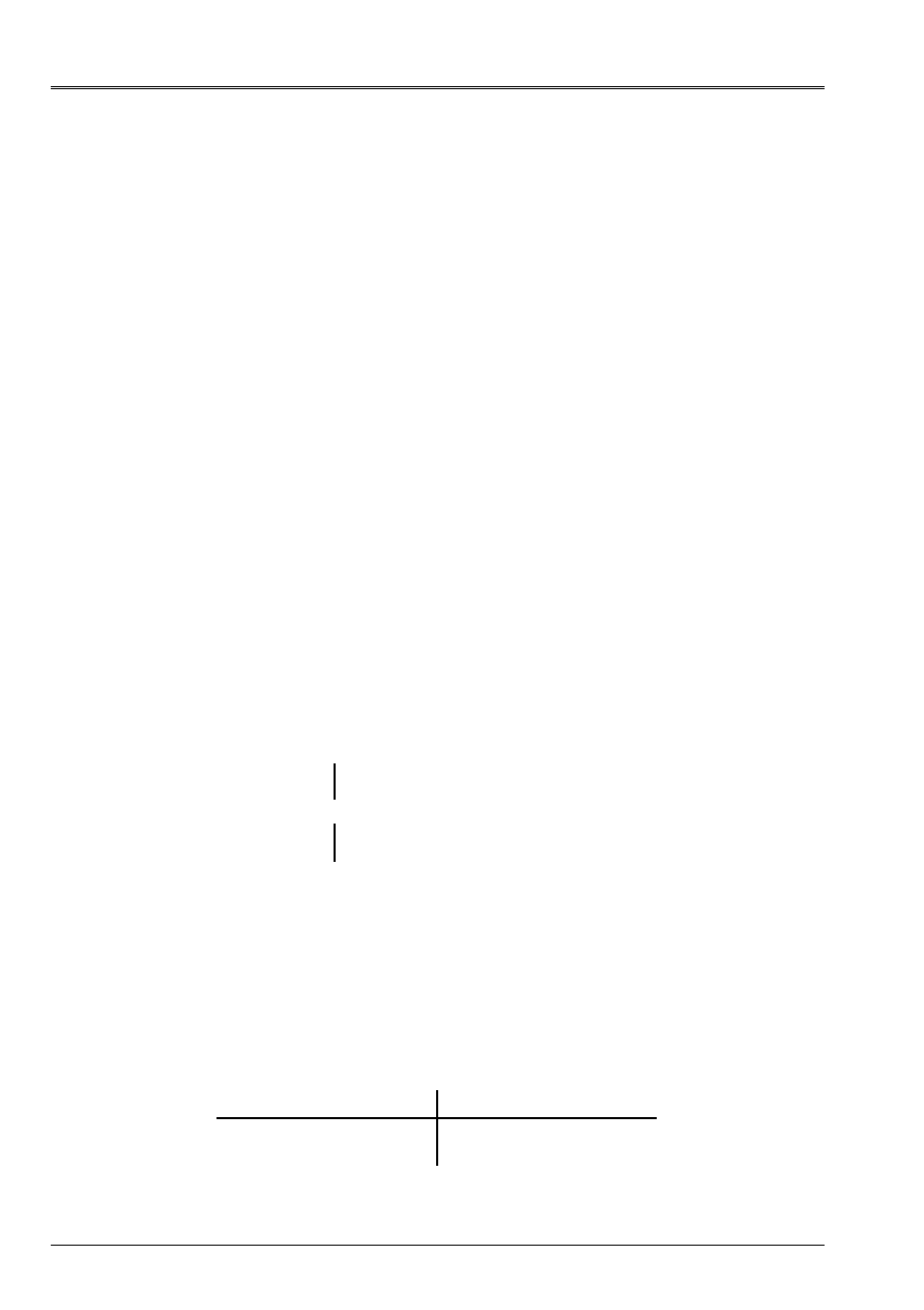
Code_Aster
®
Version
8.2
Titrate:
Operators
AFFE_CHAR_MECA
and
AFFE_CHAR_MECA_F
Date:
22/02/06
Author (S):
X. DESROCHES
Key
:
U4.44.01-I1
Page
:
66/92
Instruction manual
U4.4- booklet: Modeling
HT-62/06/004/A
4.36 Key word
DDL_POUTRE
4.36.1 Drank
Key word factor usable to lock
DDL
in a local reference mark of a beam.
The local reference mark of a beam is defined:
·
by the axis
X
determined by the mesh to which the node belongs. The mesh is directed towards
the specified node. To avoid the indetermination, it is necessary that the node to which relates
condition belongs to only one
SEG
. In the case or it belongs to several meshs,
the user defines the mesh giving the local orientation.
·
by
VECT_Y
: a vector of which projection on the orthogonal level with the axis
X
the axis defines
Y
.
The axis
Z
is given using
X
and
Y
·
by
ANGL_VRIL
: angle of spin, given in degrees, makes it possible to direct a local reference mark around
axis
X
.
4.36.2 Syntax
·
for
AFFE_CHAR_MECA
DDL_POUTRE
=_F
(
|
NODE =
lno,
[l_noeud]
|
GROUP_NO
= lgno,
[l_gr_noeud]
|
DX
=
ux
,
[R]
|
DY
=
uy
,
[R]
|
DZ
=
uz
,
[R]
|
DRX
=
X
,
[R]
|
DRY
=
y
,
[R]
|
DRZ
=
Z
,
[R]
# definition of the local reference mark
|
NET =
lma,
[l_maille]
|
GROUP_MA
= lgma,
[l_gr_maille]
/
ANGL_VRIL
=
G,
[R]
/
VECT_Y
=
(V1,
V2,
V3)
[l_R]
)
4.36.3 Operands
DX
=
ux
DY
=
uy
Value of the component of displacement in imposed translation
on the specified nodes
DZ
=
uz
DRX
=
X
DRY
=
y
Value of the component of displacement in rotation imposed on
specified nodes
DRZ
=
Z
ANGL_VRIL
= G
angle of spin, given in degrees, makes it possible to direct a local reference mark around axis X.
VECT_Y = (V1, V2, V3)
vector whose projection on the orthogonal level with axis X defines axis Y.
Axis Z is given using X and Y
4.36.4 Modelings and meshs
This loading applies to the types of meshs and following modelings:
Net Modélisation
SEG2 POU_D_T,
POU_C_T,
POU_D_TG, POU_D_E,
POU_D_TGM
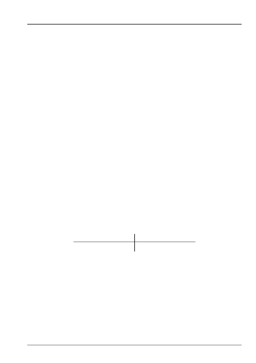
Code_Aster
®
Version
8.2
Titrate:
Operators
AFFE_CHAR_MECA
and
AFFE_CHAR_MECA_F
Date:
22/02/06
Author (S):
X. DESROCHES
Key
:
U4.44.01-I1
Page
:
67/92
Instruction manual
U4.4- booklet: Modeling
HT-62/06/004/A
4.37 Key word
FORCE_TUYAU
4.37.1 Drank
Key word factor usable to apply a pressure to elements pipe, defined by one or
several meshs or of the groups of meshs.
4.37.2 Syntax
·
AFFE_CHAR_MECA:
|
FORCE_TUYAU=_F (
/ALL =
“YES”,
/
|
NET =
lma,
[l_maille]
|
GROUP_MA
= lgma,
[l_gr_maille]
CLOSE =
p,
[R]
)
·
AFFE_CHAR_MECA_F:
|
FORCE_TUYAU=_F (
/ALL =
“YES”,
/
|
NET =
lma,
[l_maille]
|
GROUP_MA
= lgma,
[l_gr_maille]
CLOSE =
PF,
[function]
)
4.37.3 Operand
CLOSE =
p (PF),
Value of the imposed pressure (real or function).
p is positive when the pressure is internal with piping.
4.37.4 Modelings and meshs
This loading applies to the types of meshs and following modelings:
Net Modélisation
SEG3, SEG4
SEG3
“TUYAU_3M'
“TUYAU_6M'

Code_Aster
®
Version
8.2
Titrate:
Operators
AFFE_CHAR_MECA
and
AFFE_CHAR_MECA_F
Date:
22/02/06
Author (S):
X. DESROCHES
Key
:
U4.44.01-I1
Page
:
68/92
Instruction manual
U4.4- booklet: Modeling
HT-62/06/004/A
4.38 Key word
FORCE_COQUE
4.38.1 Drank
Key word factor usable to apply surface efforts, to elements of the hull type
(DKT, DST, Q4G,…)
defined on all the mesh or one or more meshs or of the groups of
meshs.
According to the name of the operator called, the values are provided directly (
AFFE_CHAR_MECA
) or
via a concept
function
(
AFFE_CHAR_MECA_F)
.
4.38.2 Syntax
·
for
AFFE_CHAR_MECA
FORCE_COQUE
=_F
(
/ALL =
“YES”,
/
|
NET =
lma,
[l_maille]
|
GROUP_MA
= lgma,
[l_gr_maille]
/
|
FX
=
fx
,
[R]
|
FY
=
fy
,
[R]
|
FZ
=
fz
,
[R]
|
MX
=
MX
,
[R]
|
MY
=
my
,
[R]
|
MZ
=
mz
,
[R]
PLAN =/
'
MOY
',
/
“INF”,
/“SUP”,
/
“MALL”, [DEFECT]
/
CLOSE =
p,
[R]
/
|
F1
=
f1
,
[R]
|
F2
=
f2
,
[R]
|
F3
=
f3
,
[R]
|
MF1
= mf1
,
[R]
|
MF2
= mf2
,
[R]
)
·
for
AFFE_CHAR_MECA_F
FORCE_COQUE
=_F
(
/ALL =
“YES”,
/
|
NET =
lma,
[l_maille]
|
GROUP_MA
= lgma,
[l_gr_maille]
/
|
FX
= fxf
,
[function]
|
FY
= fyf
,
[function]
|
FZ
= fzf
,
[function]
|
MX
= mxf
,
[function]
|
MY
= myf
,
[function]
|
MZ
= mzf
,
[function]
PLAN =/
'
MOY
',
/
“INF”,
/“SUP”,
/
“MALL”, [DEFECT]
/
CLOSE =
PF
,
[function]
/
|
F1
= f1f
,
[function]
|
F2
= f2f
,
[function]
|
F3
= f3f
,
[function]
|
MF1
=
mf1f,
[function]
|
MF2
=
mf2f,
[function]
)
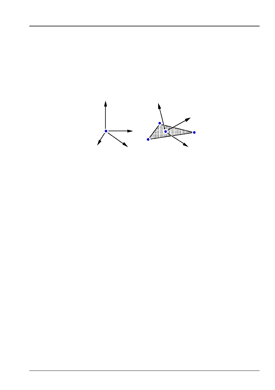
Code_Aster
®
Version
8.2
Titrate:
Operators
AFFE_CHAR_MECA
and
AFFE_CHAR_MECA_F
Date:
22/02/06
Author (S):
X. DESROCHES
Key
:
U4.44.01-I1
Page
:
69/92
Instruction manual
U4.4- booklet: Modeling
HT-62/06/004/A
4.38.3 Operands
Operands of
FORCE_COQUE
can be defined:
·
in the reference mark
TOTAL
axes
X, Y
and
Z
,
·
in a reference mark of reference defined on each mesh or groups of mesh (definite reference mark
on the variety); this reference mark is built around the normal with the element of hull (
Z
ref.
)
and of a fixed direction
(X
ref.
)
(for the group of mesh) defined by the key word
ANGL_REP
at the same time as the thickness of the hull (see key word factor
HULL
operator
AFFE_CARA_ELEM
[U4.42.01]).
1
X
Y
Z
ANGL_REP: (45. 0.)
2
3
X
ref.
(1)
y
ref.
(2)
Z
ref.
(3)
/
|
fx
:
Force according to
X
[R]
or
[function]
|
fy
:
Force according to
Y
[R]
or
[function]
|
fz
:
Force according to
Z
[R]
or
[function]
|
MX
:
Moment of axis
X
[R]
or
[function]
|
my
:
Moment of axis
Y
[R]
or
[function]
|
mz
:
Moment of axis
Z
[R]
or
[function]
/
p
:
Normal pressure with the hull
[R]
or
[function]
/
|
f1
:
Effort of membrane according to
xref [R]
or
[function]
|
f2
:
Effort of membrane according to
yref
[R]
or
[function]
|
f3
:
Following normal effort
zref
[R]
or
[function]
|
mf1
:
Bending moment of axis
X
[R]
or
[function]
|
mf2
:
Bending moment of axis
Y
[R]
or
[function]
Let us note that one must remain homogeneous in each occurrence of the key word factor
FORCE_COQUE
: that is to say all in component of effort in the reference mark
TOTAL
that is to say all in component
of effort in the reference mark of definition of the hull.
The pressure applied is positive according to the contrary direction of the normal to the element (defined by
the first 3 nodes of each mesh (cf [§4.25.3])).
PLAN
=
/
'
MOY
',
/
“INF”,
/
“SUP”,
/
“MALL”, [DEFECT]
Allows to define a torque of efforts on the average, lower, higher level or of the mesh.
If one notes D offsetting and H the thickness of the hull,
(F2X, F2Y, F2Z, m2 X, m2 Y, m2 Z) the torque of the efforts on the level defined by the user (i.e.
excentré)
(F1X, F1Y, F1Z, M1X, M1Y, M1Z) the torque of the efforts in the plan of the mesh
The formulas of passage are as follows:
·
if the plan of calculation is the plan of the mesh:
F2 = F1
M2 = M1
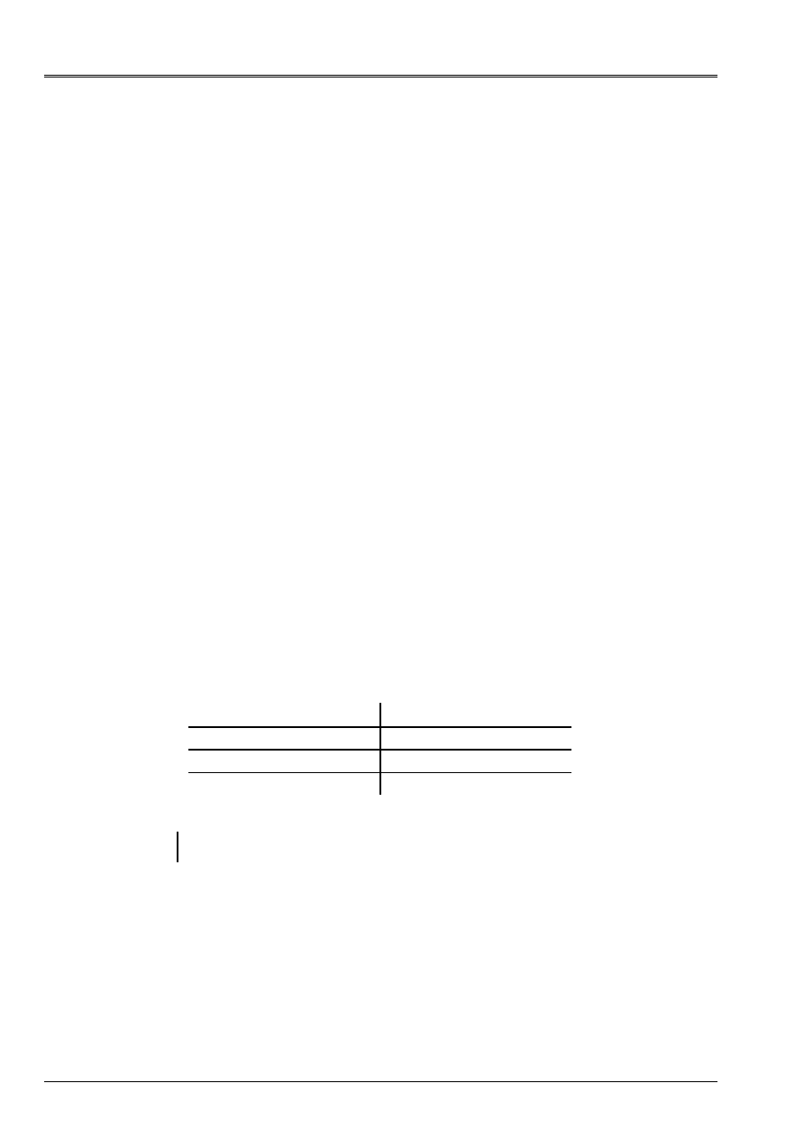
Code_Aster
®
Version
8.2
Titrate:
Operators
AFFE_CHAR_MECA
and
AFFE_CHAR_MECA_F
Date:
22/02/06
Author (S):
X. DESROCHES
Key
:
U4.44.01-I1
Page
:
70/92
Instruction manual
U4.4- booklet: Modeling
HT-62/06/004/A
·
if the plan of calculation is the excentré average layer:
F2 = F1
M2 X = M1X dxF1Y
M2 Y = M1Y + dxF1X
·
if the plan of calculation is the excentré higher layer:
F2 = F1
M2 X = M1X
X F1Y
M2 Y = M1Y +
X F1X
·
if the plan of calculation is the excentré lower layer:
F2 = F1
M2 X = M1X
X F1Y
M2 Y = M1Y +
X F1X
/
'
MOY
'one applies the torque of efforts to the excentré average layer
/
“INF” one applies the torque of efforts to the lower skin
/“SUP” one applies the torque of efforts to the higher skin
/“MALL”
one applies the torque of efforts to the level of the plan of the mesh
4.38.4 Modelings and meshs
This loading applies to the types of meshs and following modelings:
Net Modélisation
TRIA3 QUAD4
DKT, DST
QUAD4 Q4G
TRIA7 QUAD9
COQUE_3D
Note:
This loading is available only on one three-dimensional mesh (defined by
COOR_3D
).
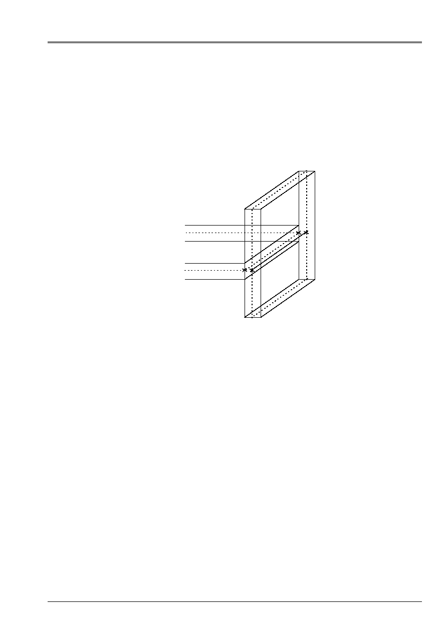
Code_Aster
®
Version
8.2
Titrate:
Operators
AFFE_CHAR_MECA
and
AFFE_CHAR_MECA_F
Date:
22/02/06
Author (S):
X. DESROCHES
Key
:
U4.44.01-I1
Page
:
71/92
Instruction manual
U4.4- booklet: Modeling
HT-62/06/004/A
4.39 Key word
LIAISON_COQUE
4.39.1 Drank
Key word factor making it possible to represent the connection enters of the hulls by means of relations
linear. The conventional approach admits that two plans with a grid in hulls are cut according to a line
who belongs to the mesh of the structure.
That has the disadvantage of twice counting the volume which is the intersection of the two hulls.
The idea is thus to stop the mesh of a hull perpendicular to a hull given to the level of
higher or lower skin of the latter.
With
1
B
1
B
2
With
2
One represented in features full volume with the hulls and in dotted lines the average plans of these hulls
(which results from the mesh).
The horizontal hull stops in A
1
With
2
and the projection of A
1
With
2
on the average level of the vertical hull
is B
1
B
2
(that one represented in full features).
The link between the 2 hulls is made by connections of solid body between the nodes in with respect to
segments A
1
With
2
and B
1
B
2
.
For example for nodes A
1
and B
1
, one will write the formula (valid in small rotations):
and equality of rotations:
4.39.2 Syntax
·
for
AFFE_CHAR_MECA
and
AFFE_CHAR_MECA_F
LIAISON_COQUE
=
_F
(
|
GROUP_MA_1 =
l_gma1
,
[l_gr_maille]
|
MAILLE_1
=
l_ma1
,
[l_maille]
|
GROUP_NO_1 =
l_gno1
,
[l_gr_noeud]
|
NOEUD_1 =
l_no1
,
[l_noeud]
|
GROUP_MA_2 =
l_gma2
,
[l_gr_maille]
|
MAILLE_2
=
l_ma2
,
[l_maille]
|
GROUP_NO_2 =
l_gno2
,
[l_gr_noeud]
|
NOEUD_2 =
l_no2
,
[l_noeud]
NUME_LAGR
=
/
“NORMAL”,
[DEFECT]
/
“AFTER”
,
)

Code_Aster
®
Version
8.2
Titrate:
Operators
AFFE_CHAR_MECA
and
AFFE_CHAR_MECA_F
Date:
22/02/06
Author (S):
X. DESROCHES
Key
:
U4.44.01-I1
Page
:
72/92
Instruction manual
U4.4- booklet: Modeling
HT-62/06/004/A
4.39.3 Operands
|
GROUP_MA_1
|
MAILLE_1
|
GROUP_NO_1
|
NOEUD_1
Using key words GROUP_MA_
1
, MAILLE_1, GROUP_NO
_1
and NOEUD_
1
, one constitutes
first list of nodes (nonredundant) representing the trace of the hull perpendicular to
the current hull.
On our example, they would be the nodes of the segment B
1
B
2
or of segment A
1
With
2
.
|
GROUP_MA_2
|
MAILLE_2
|
GROUP_NO_2
|
NOEUD_2
Using key words GROUP_MA
_2
, MESH
_2
, GROUP_NO
_2
and NODE
_2
, one constitutes
second list of nodes (nonredundant) pertaining to the perpendicular hull and in opposite
nodes of the first list. Opposite is adjusted by the program according to the criterion moreover
small distance.
On our example if the first list is consisted of the nodes of A
1
With
2
, the second list is
constituted of the nodes of B
1
B
2
.
NUME_LAGR
=
/
“NORMAL”,
[DEFECT]
/
“DEFECT”,
See key word LIAISON_SOLIDE [§4.19].
Important remarks:
1) After key words GROUP_MA
_
, MESH
_
, GROUP_NO
_
and NODE
_
, a node can
to appear several times, it is the program which is given the responsability to eliminate the occurrences
useless and thus to obtain a nonredundant list of nodes.
2) After the elimination of the useless occurrences of the nodes in the two lists of nodes,
these two lists must be imperatively equal length.
3) Meshs given after key words GROUP_MA
_1
, GROUP_MA
_2
, MESH
_1
and
NET
_2
are of the meshs of edge of the type SEG2 or SEG3 of the elements of hull and
for which one does not have inevitably affected mechanical modeling.

Code_Aster
®
Version
8.2
Titrate:
Operators
AFFE_CHAR_MECA
and
AFFE_CHAR_MECA_F
Date:
22/02/06
Author (S):
X. DESROCHES
Key
:
U4.44.01-I1
Page
:
73/92
Instruction manual
U4.4- booklet: Modeling
HT-62/06/004/A
4.40 Key word
RELA_CINE_BP
4.40.1 Drank
Key word factor allowing the definition of a loading of the type RELA_CINE_BP.
This type of loading can be defined for a mechanical system including/understanding a structure concrete
and its cables of prestressing. Initial profiles of voltage in the cables, as well as the coefficients
relations kinematics between the ddl of the nodes of the cables and the ddl of the nodes of the structure
concrete are beforehand given by operator DEFI_CABLE_BP [U4.42.04]. Concepts
cabl_precont produced by this operator brings all information necessary to
definition of the loading.
The multiple occurrences are authorized for the key word factor RELA_CINE_BP, in order to allow
in the same call to operator AFFE_CHAR_MECA to define the contributions of each one of
groups of cables having been the subject of distinct calls to operator DEFI_CABLE_BP [U4.42.04].
With each group of cables considered, defined by a concept cabl_precont, is associated one
occurrence of the key word factor RELA_CINE_BP.
The loading thus defined is then used to calculate the state of balance of the unit structure concrete/
cables of prestressing. However, the taking into account of this type of loading is not effective
in all the operators of resolution. The loading of the type RELA_CINE_BP is not recognized for
the moment that by operator STAT_NON_LINE [U4.51.03], option COMP_INCR exclusively.
4.40.2 Syntax (AFFE_CHAR_MECA only)
RELA_CINE_BP
=_F
(
CABLE_BP
=
cabl_pr,
[cabl_precont]
SIGM_BPEL
=
/
“YES”,
/
“NOT”,
[DEFECT]
RELA_CINE
=
/
“YES”,
[DEFECT]
/
“NOT”,
)
4.40.3 Operands
CABLE_BP = cabl_pr
Concept of the cabl_precont type produces by operator DEFI_CABLE_BP [U4.42.04]. This concept
bring on the one hand the card of the initial stresses in the elements of the cables of same
group, and in addition the lists of the relations kinematics between the ddl of the nodes of these
cables and ddl of the nodes of the structure concrete.
SIGM_BPEL
=
/
“YES”,
/
“NOT”,
[DEFECT]
Indicator of the text type by which one specifies the taking into account of the initial stresses in
cables; the default value is “NOT”.
In the case “NOT”, only the liaisonnement kinematic one is taken into account. It is useful if one
connect STAT_NON_LINE whereas one has cables of prestressing. For the first
STAT_NON_LINE it is necessary to have put
“YES”
, so that one sets up the voltage in
cables. On the other hand, for the following STAT_NON_LINE, one should not regard as
loading that the connections kinematics and thus to define the loading with SIGM_BPEL =
“NOT”, if not the voltage is counted twice.
Since the restitution the macro one to put in voltage the cables, the user would not have any more
to need to do one
AFFE_CHAR_MECA
with
SIGM_BPEL = “YES”
, that should thus avoid
risks of error.
RELA_CINE
=
/
“YES”,
[DEFECT]
/
“NOT”,
Indicator of the text type by which one specifies the taking into account of the relations kinematics enters
ddl of the nodes of the cables and ddl of the nodes of the structure concrete; the default value is
“YES”
.
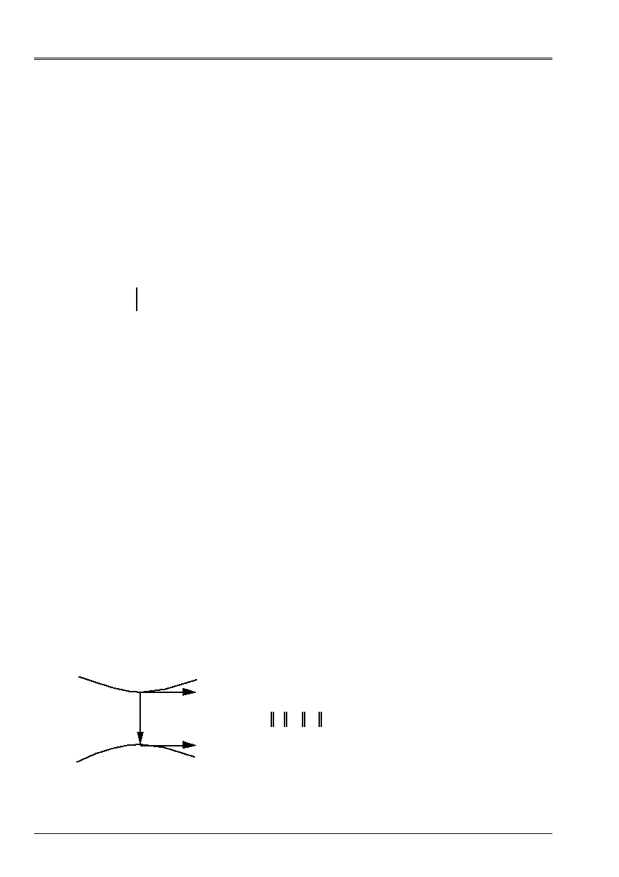
Code_Aster
®
Version
8.2
Titrate:
Operators
AFFE_CHAR_MECA
and
AFFE_CHAR_MECA_F
Date:
22/02/06
Author (S):
X. DESROCHES
Key
:
U4.44.01-I1
Page
:
74/92
Instruction manual
U4.4- booklet: Modeling
HT-62/06/004/A
4.41 Key word
FORCE_ELEC
4.41.1 Drank
Key word factor usable to apply the force of LAPLACE acting on a main conductor,
had with the presence of a secondary conductor right (not being based on part of mesh
Aster) compared to this main conductor.
In fact, the loading defined by
FORCE_ELEC
a module has which must be multiplied by the function
temporal of intensity specified by the operator
DEFI_FONC_ELEC
[U4.MK.10] to represent
really the force of LAPLACE.
The main conductor is based on whole or part of the Aster mesh made up of linear elements
in space and defined in this operator by one or more meshs, of the groups of meshs or
totality of the mesh.
Note:
When the secondary conductor is not rectilinear the key word will be used
INTE_ELEC
[§4.40].
4.41.2 Syntax
FORCE_ELEC = _F
(
/ALL =
“YES”,
/
|
NET =
lma,
[l_maille]
|
GROUP_MA
= lgma,
[l_gr_maille]
/
|
FX
=
fx,
[R]
|
FY
=
fy,
[R]
|
FZ
=
fz,
[R]
/
POSITION = “PARA”,
/
TRANS
=
(ux, uy, uz,),
[l_R]
/
DIST =
D,
[R]
/
POINT2
=
(x2, y2, z2,),
[l_R]
/
POSITION = “FINISHED”,
POINT1
=
(x1, y1, z1,),
[l_R]
POINT2
=
(x2, y2, z2,),
[l_R]
/
POSITION = “INFI”
POINT1
=
(x1, y1, z1,),
[l_R]
POINT2
=
(x2, y2, z2,),
[l_R]
)
4.41.3 Function of space
The function of space composing the linear density of force of LAPLACE exerted in a point
conductor 1 (main conductor) by the elements of conductor 2 (secondary conductor) is:
1
2
M
ds
2
E
2
E
1
R
I
2
I
1
with
E
1
= E
2
= 1
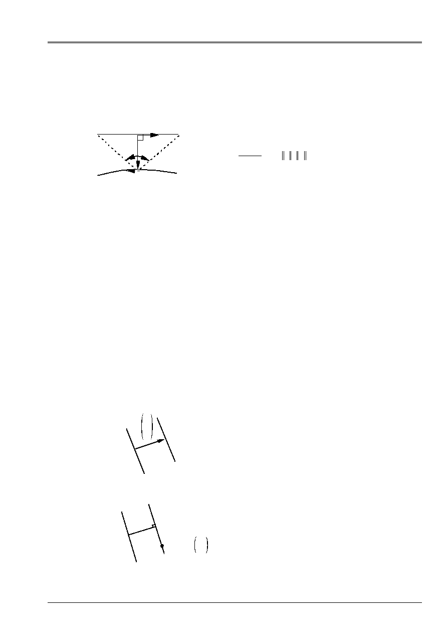
Code_Aster
®
Version
8.2
Titrate:
Operators
AFFE_CHAR_MECA
and
AFFE_CHAR_MECA_F
Date:
22/02/06
Author (S):
X. DESROCHES
Key
:
U4.44.01-I1
Page
:
75/92
Instruction manual
U4.4- booklet: Modeling
HT-62/06/004/A
In the case of a secondary right and finished conductor, this expression becomes:
1
2
M
P1
P2
2
D
E
2
E
1
with
N
E
D
D N
=
=
=
2
1
D
D
,
,
In the particular case of the secondary conductor infinite right,
tend towards
, one has
then:
4.41.4 Operands
|
FORCE_ELEC
If there are several secondary conductors infinite and parallel with the conductor
the main thing (key words
COUR_PRIN
and
COUR_SECO
in the control
DEFI_FONC_ELEC
) one
directly specify the components of the direction of the force of LAPLACE which must be
normalized to 1.
/
|
FX = fx,
fx2 + fy2 + fz2 = 1.
|
FY = fy,
(fx, fy, fz)
colinéaire with the force of LAPLACE
|
FZ = fz,
If not, the direction of the force of LAPLACE can be defined by the position of the conductor
single secondary compared to the elements of the main conductor.
/
POSITION
/
“PARA”
The secondary conductor is considered infinite and parallel with the main conductor. One
can define its position in two manners:
/TRANS: (ux uy uz)
1
2
U
U
X
U
y
U
Z
main conductor 1 with the conductor
secondary 2
U
U
X
U
y
U
Z
the translation defines bringing
/
DIST
=
D,
/
POINT2
=
(x2, y2, z2
),
1
2
D
POINT2
X
2
y
2
Z
2
The secondary conductor 2 is defined
by its distance to the conductor 1 and one
second point.
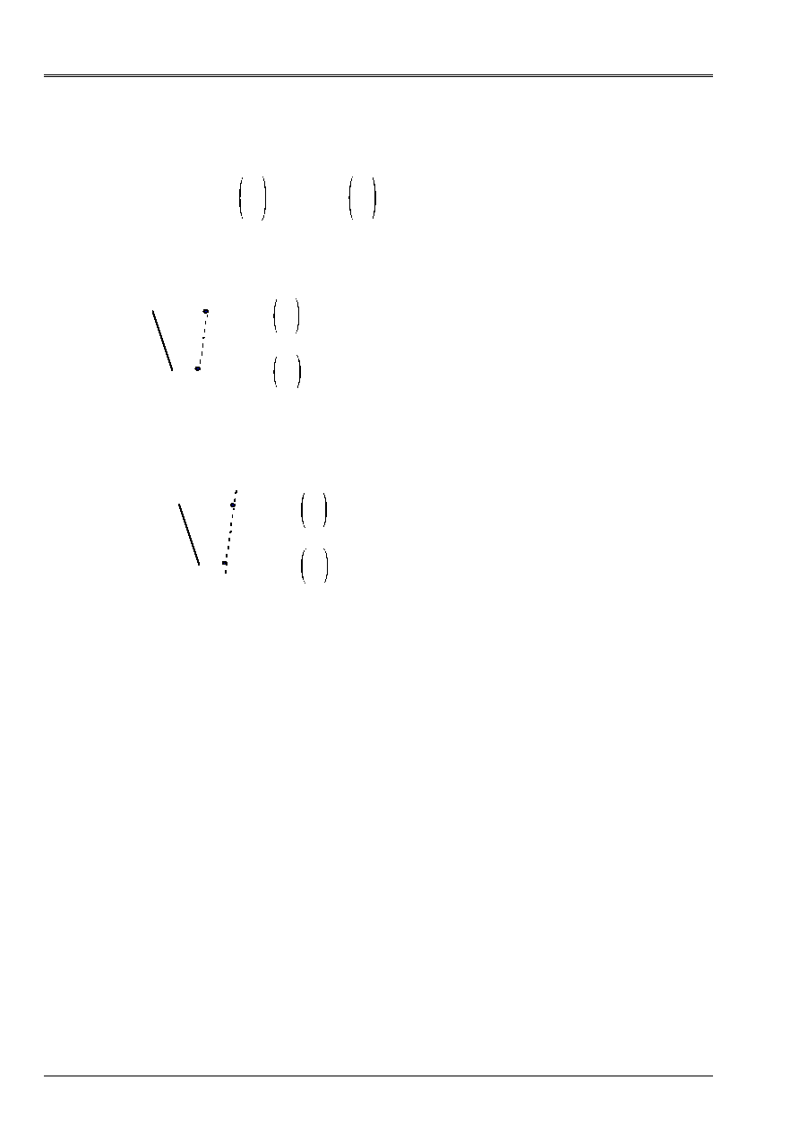
Code_Aster
®
Version
8.2
Titrate:
Operators
AFFE_CHAR_MECA
and
AFFE_CHAR_MECA_F
Date:
22/02/06
Author (S):
X. DESROCHES
Key
:
U4.44.01-I1
Page
:
76/92
Instruction manual
U4.4- booklet: Modeling
HT-62/06/004/A
/
“FINISHED”
The secondary conductor is defined by two points corresponding at its ends
POINT1
X
1
y
1
Z
1
and
POINT2
X
2
y
2
Z
2
.
POINT1
=
(x1, y1, z1),
POINT2 = (x2, y2, z2),
1
2
1
POINT2
X
2
y
2
Z
2
POINT1
X
1
y
1
Z
1
/
“INFI”
The secondary conductor is defined by two unspecified points
POINT1
and
POINT2
.
POINT1
=
(x1, y1, z1),
POINT2 = (x2, y2, z2),
1 2
1
POINT2
X
2
y
2
Z
2
POINT1
X
1
y
1
Z
1
In both cases, it is preferable to choose
POINT1
and
POINT2
such as the current circulates
of
POINT1
with
POINT2
.
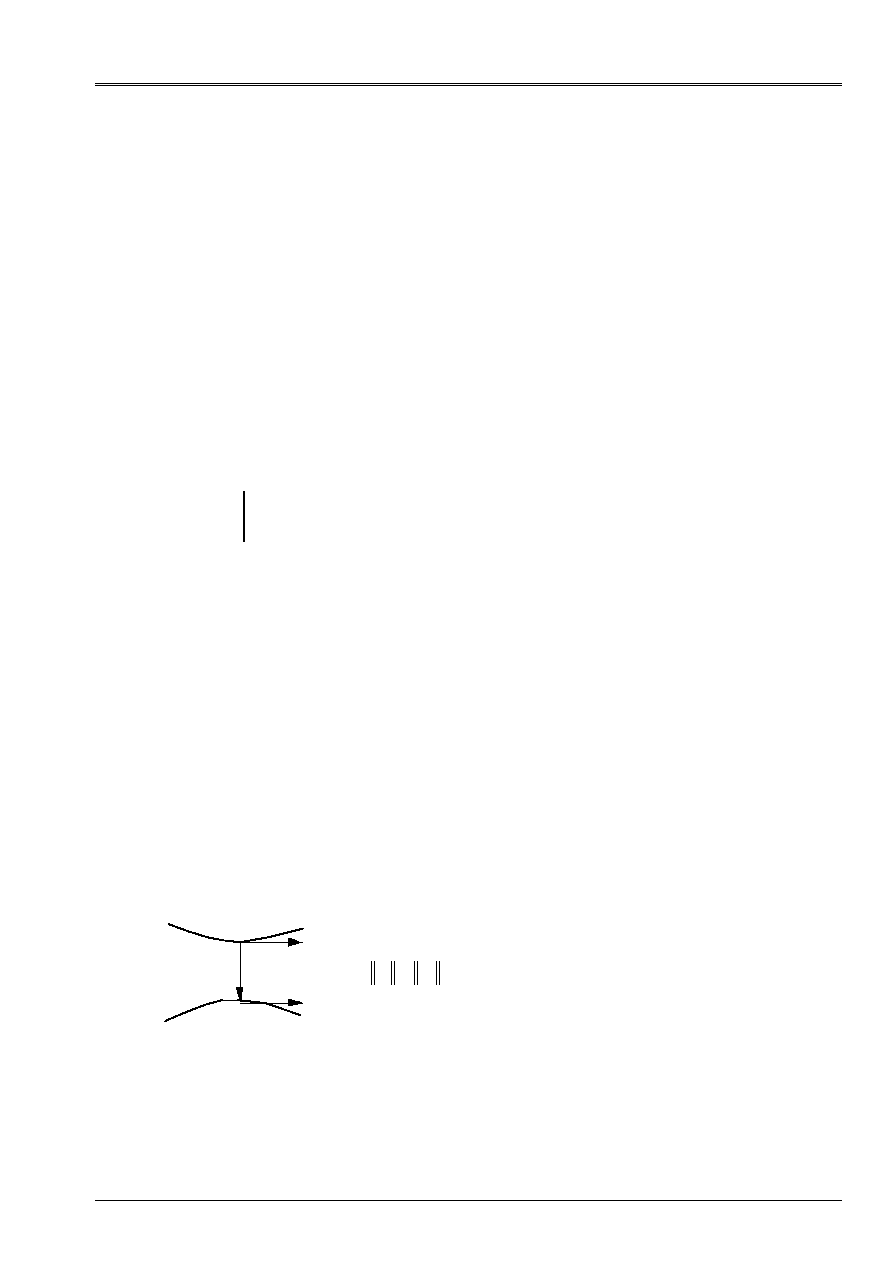
Code_Aster
®
Version
8.2
Titrate:
Operators
AFFE_CHAR_MECA
and
AFFE_CHAR_MECA_F
Date:
22/02/06
Author (S):
X. DESROCHES
Key
:
U4.44.01-I1
Page
:
77/92
Instruction manual
U4.4- booklet: Modeling
HT-62/06/004/A
4.42 Key word
INTE_ELEC
4.42.1 Drank
Key word factor usable to apply the force of LAPLACE acting on a main conductor,
had with the presence of a secondary conductor not necessarily right compared to this conductor
the main thing.
In fact, the loading defined by
INTE_ELEC
a module has which must be multiplied by the function
temporal of intensity specified by the operator
DEFI_FONC_ELEC
[U4.MK.10] to represent
really the force of LAPLACE.
The main conductor is based on part of Aster mesh made up of linear elements in
space and defined in this operator by one or more meshs, of the groups of meshs or totality
mesh.
The secondary conductor is also based on part of Aster mesh made up of elements
linear in the space and also specified in this operator by one or more meshs, of
groups of meshs, or by a translation (or a symmetry planes) compared to the conductor
the main thing.
Note:
The difference of the use of the key word
INTE_ELEC
compared to the key word
FORCE_ELEC
reside in the fact that the geometry of the secondary conductor can not be rectilinear
and is based on part of Aster mesh which one describes here.
4.42.2 Syntax
INTE_ELEC
=_F
(
/ALL =
“YES”,
/
|
NET =
lma,
[l_maille]
|
GROUP_MA
= lgma,
[l_gr_maille]
/
|
MAILLE2 = lma,
[l_maille]
|
GROUP_MA2 = lgma,
[l_gr_maille]
/
TRANS
=
(ux, uy, uz),
[l_R]
/
SYME
=
(x0, y0, z0, ux, uy, uz),
[l_R]
)
4.42.3 Function of space
The function of space composing the linear density of forces of LAPLACE exerted in a point
conductor 1 (main conductor) by the elements of conductor 2 (secondary conductor)
can express itself:
1
2
M
ds
2
E
2
E
1
R
I
2
I
1
with
E
E
1
2
1
=
=
For each element I of the secondary conductor, one calculates his contribution starting from the expression
the preceding one and one summon:
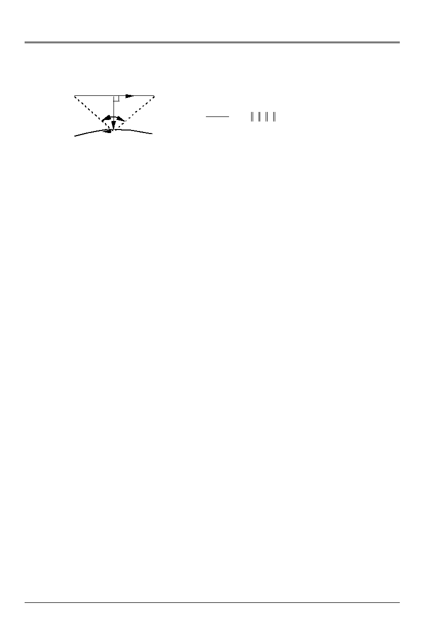
Code_Aster
®
Version
8.2
Titrate:
Operators
AFFE_CHAR_MECA
and
AFFE_CHAR_MECA_F
Date:
22/02/06
Author (S):
X. DESROCHES
Key
:
U4.44.01-I1
Page
:
78/92
Instruction manual
U4.4- booklet: Modeling
HT-62/06/004/A
1
2
M
P1
P2
2
D
E
2
E
1
with
N
E
D
D N
=
=
=
2
1
D
D
,
,
4.42.4 Operands ALL/MESH/GROUP_MA/MAILLE2/GROUP_MA2/TRANS/SYME
ALL, MESH, GROUP_MA:
The geometry of the main conductor defines where the loading is affected.
MAILLE2, GROUP_MA2:
The geometry of the secondary conductor defines.
TRANS
:
A translation of the main conductor defines in the secondary conductor.
SYME
:
A symmetry compared to a plan (given by a point defines (
X
0
y
0
Z
0
) and the normal (
U
X
U
y
U
Z
)
commune with the main conductor and the secondary conductor).
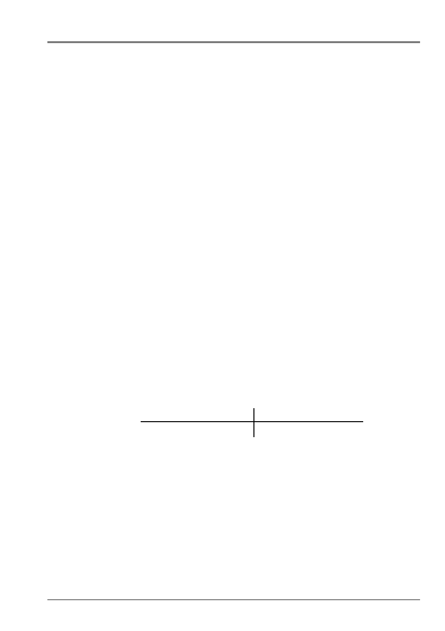
Code_Aster
®
Version
8.2
Titrate:
Operators
AFFE_CHAR_MECA
and
AFFE_CHAR_MECA_F
Date:
22/02/06
Author (S):
X. DESROCHES
Key
:
U4.44.01-I1
Page
:
79/92
Instruction manual
U4.4- booklet: Modeling
HT-62/06/004/A
4.43 Key word
IMPE_FACE
(Phenomenon
“ACOUSTIC”
)
4.43.1 Drank
The key word factor
IMPE_FACE
allows to apply an acoustic impedance, with a face defined by
one or more meshs or groups of meshs of the triangle type or quadrangle.
The values are directly given if the operator called is
AFFE_CHAR_MECA
; if it is
AFFE_CHAR_MECA_F
, they come from a concept of the type
function
.
4.43.2 Syntax
·
for
AFFE_CHAR_MECA
IMPE_FACE
=_F
(
|
NET =
lma, [l_maille]
|
GROUP_MA=
lgma,
[l_gr_maille]
IMPE
=
Q,
[R]
)
·
for
AFFE_CHAR_MECA_F
IMPE_FACE
=_F
(
|
NET =
lma, [l_maille]
|
GROUP_MA=
lgma,
[l_gr_maille]
IMPE
=
Qf,
[function]
)
4.43.3 Operand IMPE_FACE
IMPE_FACE = Q (Qf)
Acoustic impedance applied to the face.
4.43.4 Modelings and meshs
The loading applies to the types of meshs and following modelings:
Type of Mesh
Modeling
TRIA3, TRIA6
QUAD4, QUAD8, QUAD9
3d_FLUIDE
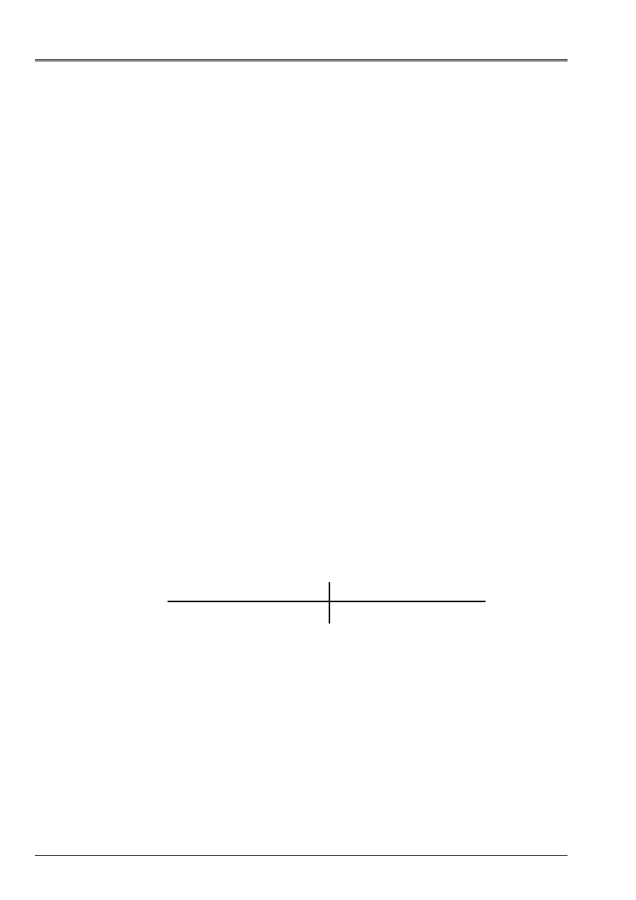
Code_Aster
®
Version
8.2
Titrate:
Operators
AFFE_CHAR_MECA
and
AFFE_CHAR_MECA_F
Date:
22/02/06
Author (S):
X. DESROCHES
Key
:
U4.44.01-I1
Page
:
80/92
Instruction manual
U4.4- booklet: Modeling
HT-62/06/004/A
4.44 Key word
VITE_FACE
(Phenomenon
“ACOUSTIC”
)
4.44.1 Drank
The key word factor
VITE_FACE
allows to apply normal speeds, with a face defined by one
or several meshs or groups of meshs of the triangle type or quadrangle.
The values are directly given if the operator called is
AFFE_CHAR_MECA
, if it is
AFFE_CHAR_MECA_F
, they come from a concept of the function type.
4.44.2 Syntax
·
for
AFFE_CHAR_MECA
VITE_FACE
=_F
(
|
NET =
lma,
[l_maille]
|
GROUP_MA=
lgma,
[l_gr_maille]
VNOR
=
V,
[R]
)
·
for
AFFE_CHAR_MECA_F
VITE_FACE
=_F
(
|
NET =
lma,
[l_maille]
|
GROUP_MA=
lgma,
[l_gr_maille]
VNOR
=
Vf,
[function]
)
4.44.3 Operand VNOR
VNOR = V (Vf)
Normal speed applied to the face.
4.44.4 Modelings and meshs
The loading applies to the types of meshs and following modelings:
Type of Mesh
Modeling
TRIA3, TRIA6
QUAD4, QUAD8, QUAD9
3d_FLUIDE

Code_Aster
®
Version
8.2
Titrate:
Operators
AFFE_CHAR_MECA
and
AFFE_CHAR_MECA_F
Date:
22/02/06
Author (S):
X. DESROCHES
Key
:
U4.44.01-I1
Page
:
81/92
Instruction manual
U4.4- booklet: Modeling
HT-62/06/004/A
4.45 Key word
ONDE_PLANE
4.45.1 Drank
Key word factor usable to impose a seismic loading by plane wave, corresponding to
loadings classically met during calculations of interaction ground-structure by the equations
integrals (see [R4.05.01]).
4.45.2 Syntax (AFFE_CHAR_MECA_F only)
ONDE_PLANE =_F
(
TYPE_ONDE
= ty, [txm]
DIRECTION
=
(kx, ky, kz),
[l_R]
DIST_ORIG
=
H,
[R]
FONC_SIGNAL
=
F,
[function]
)
4.45.3 Operands
TYPE_ONDE
= ty,
Type of the wave: “P”
wave of compression
“SV”
waves of shearing
“HS”
waves of shearing
DIRECTION
= (kx, ky, kz),
Direction of the wave.
DIST_ORIG
= H,
Outdistance main face of wave at the origin at the initial moment.
FONC_SIGNAL = F,
Derived from the profile of the wave:
for
.
In harmonic, a wave planes elastic is characterized by its direction, its pulsation and sound
type (wave P for the waves of compression, waves SV or HS for the waves of shearing).
In transient, the data of the pulsation, corresponding to a standing wave in time, must
to be replaced by the data of a profile of displacement which one will take into account
propagation in the course of time in the direction of the wave.
More precisely, one characterizes:
·
a wave P by the function
·
a wave S by the function
With:
·
K
, unit vector of direction
·
then represent the profile of the wave given according to the direction
K
.
Caution: it is the derivative
that the user gives in FONC_SIGNAL.
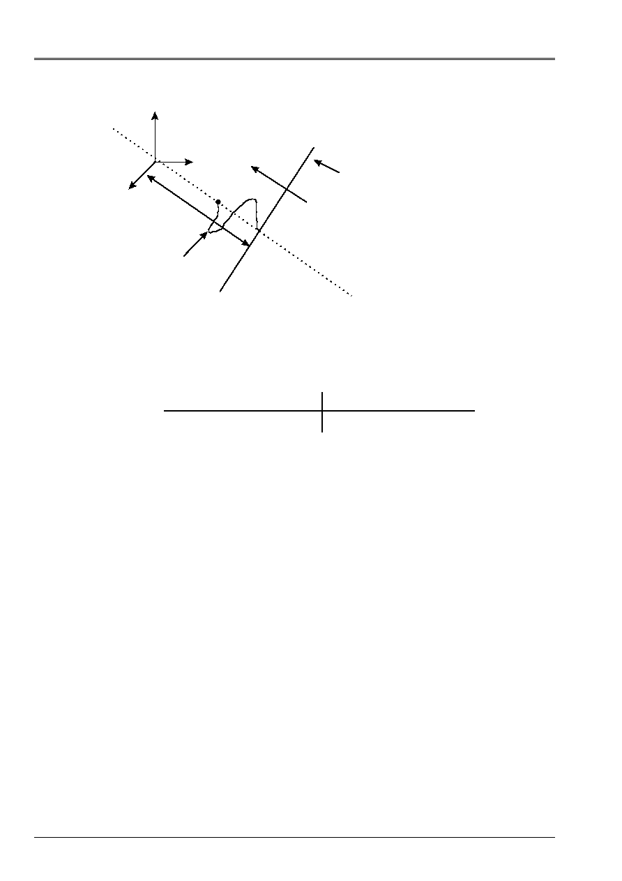
Code_Aster
®
Version
8.2
Titrate:
Operators
AFFE_CHAR_MECA
and
AFFE_CHAR_MECA_F
Date:
22/02/06
Author (S):
X. DESROCHES
Key
:
U4.44.01-I1
Page
:
82/92
Instruction manual
U4.4- booklet: Modeling
HT-62/06/004/A
O
H
Function
F
K
“Main” face of wave
corresponding at the origin
profile
H
0
is the distance from the main face of wave in the beginning O, carried by the directing vector of the wave with
the initial moment of calculation, H the distance from the main face of wave in the beginning O, one moment
unspecified.
4.45.4 Modelings and meshs
Type of Mesh
Modeling
MECA_FACE_ *
MEPLSE2, MEPLSE3
3d_ABSO
2d_ABSO
Code_Aster
®
Version
8.2
Titrate:
Operators
AFFE_CHAR_MECA
and
AFFE_CHAR_MECA_F
Date:
22/02/06
Author (S):
X. DESROCHES
Key
:
U4.44.01-I1
Page
:
83/92
Instruction manual
U4.4- booklet: Modeling
HT-62/06/004/A
4.46 Key word
ONDE_FLUI
(Phenomenon
“ACOUSTIC”
)
4.46.1 Drank
The key word factor
ONDE_FLUI
allows to apply an amplitude of pressure of incidental wave
sinusoidal arriving normally at a face defined by one or more meshs or groups of
meshs.
4.46.2 Syntax
·
for
AFFE_CHAR_MECA
ONDE_FLUI
=_F
(
|
NET =
lma,
[l_maille]
|
GROUP_MA=
lgma,
[l_gr_maille]
NEAR
=
P,
[R]
)
·
for
AFFE_CHAR_MECA_F
Not developed.
4.46.3 Operand NEAR
CLOSE = P,
Amplitude of pressure of sinusoidal incidental wave arriving normally at the face.
4.46.4 Modelings and meshs
The loading applies to the types of meshs and following modelings:
Type of Mesh
Modeling
TRIA3, TRIA6
QUAD4, QUAD8, QUAD9
3d_FLUIDE
SEG2, SEG3
2d_FLUIDE, AXIS_FLUIDE

Code_Aster
®
Version
8.2
Titrate:
Operators
AFFE_CHAR_MECA
and
AFFE_CHAR_MECA_F
Date:
22/02/06
Author (S):
X. DESROCHES
Key
:
U4.44.01-I1
Page
:
84/92
Instruction manual
U4.4- booklet: Modeling
HT-62/06/004/A
4.47 Key word
FLUX_THM_REP
4.47.1 Drank
Key word factor usable to apply to a field of continuous medium 2D or 3D defined by
meshs or groups of meshs a heat transfer rate and/or a fluid contribution of mass (hydraulic flow).
4.47.2 Syntax
·
for
AFFE_CHAR_MECA
FLUX_THM_REP
=_F
(
/ALL =
“YES”,
/
|
NET
= lma
,
[l_maille]
|
GROUP_MA
= lgma,
[l_gr_maille]
|
FLUN =
T
,
[R]
|
FLUN_HYDR1 =
E
,
[R]
|
FLUN_HYDR2 =
v
,
[R]
)
·
for
AFFE_CHAR_MECA_F
FLUX_THM_REP
=_F
(
/ALL =
“YES”,
/
|
NET
= lma
,
[l_maille]
|
GROUP_MA
= lgma,
[l_gr_maille]
|
FLUN =
Tf,
[function]
|
FLUN_HYDR1 =
EFF,
[function]
|
FLUN_HYDR2 =
vf,
[function]
)
4.47.3 Operands
|
FLUN
=
T,
Value of the heat transfer rate
with:
: mass enthalpy of the fluid
: mass enthalpy of the vapor
: mass enthalpy of the air
and
are below definite hydraulic flows
|
FLUN_HYDR1
=
E,
Value of the hydraulic flow associated the component water
|
FLUN_HYDR2
=
v,
Value of the hydraulic flow associated the component air
with:
: density of the fluid
: density of the vapor
: pressure of fluid (PRE1)
: steam pressure (PRE2)
Code_Aster
®
Version
8.2
Titrate:
Operators
AFFE_CHAR_MECA
and
AFFE_CHAR_MECA_F
Date:
22/02/06
Author (S):
X. DESROCHES
Key
:
U4.44.01-I1
Page
:
85/92
Instruction manual
U4.4- booklet: Modeling
HT-62/06/004/A
4.47.4 Modelings and meshs
Normal flows apply to the types of meshs and following modelings:
Type of Mesh
Modeling
SEG2
SEG3
FACE8
D_PLAN_YYYY
AXIS_YYYY, D_PLAN_YYYY
3d_YYYY
with YYYY = THM or THH or THHM or HM or HHM.
4.48 Key word
HARLEQUIN
4.48.1 Drank
Key word factor defining the parameters of the method Harlequin. This method consists in connecting
models by volume. A priori, any combination of mesh, interpolations and
kinematics is possible. It thus makes it possible to enrich a model locally, to create the junction
between two models, to substitute a model by another locally. This junction is ensured by
weighting of the work of the elastic forces on space mediator: the trace of one of the two models
on the area of joining.
4.48.2 Restrictions of use
Only two models can be superimposed on the same place. Only voluminal models
(3D), surface (2D) and of hulls (2D and 3D) are authorized.
4.48.3 Syntax
·
for
AFFE_CHAR_MECA
only
HARLEQUIN
: (
GROUP_MA_1
=
gma1,
[gr_maille]
GROUP_MA_2
=
gma2,
[gr_maille]
GROUP_MA_COLL
=
gma
,
[gr_maille]
JOINING =
/
“COARSE”,
[DEFECT]
/“FINE”,
/“GROUP_MA1”,
/“GROUP_MA2”,
/
POIDS_1 =
1
,
[R]
/
POIDS_2 =
2
,
[R]
/
POIDS_GROSSIER =
F
,
[R]
/
POIDS_FIN
=
G
,
[R]
CARA_ELEM
=
will cara,
[cara_elem]
)
4.48.4 Operands
GROUP_MA_1 = gma1
GROUP_MA_2 = gma2
Names of the group of meshs defining the models overlapping. The relative position of
borders, of the nodes and the meshs belonging to these two models is a priori
independent. No node nor no mesh must be shared by the two models.
GROUP_MA_1
and
GROUP_MA_2
play the same part, without distinction.

Code_Aster
®
Version
8.2
Titrate:
Operators
AFFE_CHAR_MECA
and
AFFE_CHAR_MECA_F
Date:
22/02/06
Author (S):
X. DESROCHES
Key
:
U4.44.01-I1
Page
:
86/92
Instruction manual
U4.4- booklet: Modeling
HT-62/06/004/A
GROUP_MA_COLL = gma
Group meshs defining the area where the two models are connected. This area must
normally to correspond to meshs of GROUP_MA_1 or GROUP_MA_2 pertaining to
the area of recovery of the two fields. It is however possible that it overflows of this
area of superposition. If the key word is not indicated, the exact area of superposition is
reserve in the algorithm.
JOINING =
Choice of the model used to define the multipliers of Lagrange of joining (
GROUP_MA_1
or
GROUP_MA_2
restricted at the area of joining). A comparison of the average volume of
meshs of the two models allows also the employment of
END
or
COARSE
.
¨/
POIDS_1
=
1,
¨/
POIDS_2
=
2,
¨/
POIDS_FIN
=
F,
¨/
POIDS_GROSSIER =
G,
Reality lain strictly between 0. and 1. It makes it possible to define the value of the functions of
weighting in the area of superposition. POIDS_i corresponds to the weight of model I.
The data of
1 or 2 makes it possible to describe the couple (1,2) such as:
(
1,2) = (1,1 - 1) or (1 - 2, 2)
CARA_ELEM =
Field of elementary characteristics resulting from AFFE_CARA_ELEM (thicknesses for
hulls, sections for the beams). To specify obligatorily when one of the two models
is composed of hulls.
4.48.5 Examples and consultings of use
Operation of junction of models:
HARLEQUIN = _F (
GROUP_MA_1
=
gma1,
GROUP_MA_2
=
gma2,
[CARA_ELEM
=
will cara,]
JOINING
=
“COARSE”,
POIDS_FIN =
0.99
)
Operation of substitution (introduction of defects…) :
HARLEQUIN = _F (
GROUP_MA_1
= gma1,
# models without defect
GROUP_MA_2
= gma2,
# models with defect
[CARA_ELEM
=
will cara,]
GROUP_MA_COLL = gmac,
# crowns encircling the defect,
#
sufficient
far
defect
for
#
that
2
models
are
#
compatible
mechanically
JOINING
=
`GROUP_MA_2,
POIDS_2
=
0.9999
)

Code_Aster
®
Version
8.2
Titrate:
Operators
AFFE_CHAR_MECA
and
AFFE_CHAR_MECA_F
Date:
22/02/06
Author (S):
X. DESROCHES
Key
:
U4.44.01-I1
Page
:
87/92
Instruction manual
U4.4- booklet: Modeling
HT-62/06/004/A
4.49 Key word
GRAPPE_FLUIDE
4.49.1 Drank
Key word factor allowing the input of the design data of the fluid forces at the time of the studies of fall
of bunch.
This type of loading is specific to this kind of study. It is associated a preset mesh.
data entered via a file “include” suitable for the type of assembly of which one
study the fall of bunch. Examples of files “include” and mesh are available with
the cases tests associated with this type of loading. They count, in the form of variables pythons, them
data entered under the various single-ended spanner words of the key word factor GRAPPE_FLUIDE.
If one wishes to modify one, or several, values, it is possible to call again upon
GRAPPE_FLUIDE. According to the rule of overload, the last entered value is then that employed for
calculation.
Caution:
Even if, for purely data-processing reasons, the single-ended spanner words appear
like optional, it is necessary that all the data entered, that is to say directly
by the user, that is to say, as he it is recommended, via the file include.
4.49.2 Syntax
Applicable to
AFFE_CHAR_MECA
only:
GRAPPE_FLUIDE = _F (
# definition of the group of meshs modelizing the tube, the spider and the pencil:
GROUP_MA = “magrap”,
[gr_maille]
# definition of the higher node of the tube:
/
GROUP_NO_ORIG
= “grnori”,
[gr_noeud]
/NOEUD_ORIG =
“nonori”,
[node]
# definition of the lower node of the pencil:
/
GROUP_NO_EXTR
= “grnoex”,
[gr_noeud]
/NOEUD_EXTR =
“nonoex”,
[node]
# depth of initial depression of the pencil in the core:
Z0 =
z0, [R]
# definition of the hydraulic data:
CARA_HYDR = (
“Q”, “ROCK”, “ROD”, “ROP”, “ROMANIAN”, “ROML”, “ROG”,
“NUC”, “NUM”, “NUML”, “NUG”, “P2”, “P3”, “P4”, “CGG”, “G”
),
VALE_HYDR = (
Q, rock, rod, rop, Romanian, roml, rog,
nuc,
num,
numl,
nug,
p2, p3, p4, cgg, G), [R]
# definition of the geometrical data of bunch:
CARA_GRAPPE= (
“Me, “DTIGE”, “DTMOY”, “ROTIGE”, “LTIGE”, “LLT”, “LCT”,
“VARAI”, “RORAI”, “DCRAY”, “ROCRAY”, “LCRAY”, “LCHUT”,
“CFCM”, “CFCI”, “CFCG”, “HRUGC”, “HRUGTC”, “NCA”),
VALE_GRAPPE= (
m, dtige, dtmoy, rotige, ltige, llt, lct,
will varai,
will rorai,
dcray,
rocray,
lcray,
lchut,
cfcm,
cfci,
cfgg,
hrugg,
hrugtc,
nca),
[R]

Code_Aster
®
Version
8.2
Titrate:
Operators
AFFE_CHAR_MECA
and
AFFE_CHAR_MECA_F
Date:
22/02/06
Author (S):
X. DESROCHES
Key
:
U4.44.01-I1
Page
:
88/92
Instruction manual
U4.4- booklet: Modeling
HT-62/06/004/A
# definition of the geometrical data of the control drive:
CARA_COMMANDE
= (
“LI”, “LML”, “LG”, “LIG”, “DIML”, “DEML”, “DCSP”,
“DG”, “HRUGML”, “HRUGCSP”, “HRUGG”),
VALE_COMMANDE
= (
Li, lml, lg, lig, diml, deml, dcsp,
dg,
hrugml,
hruggcsp,
hrugg),
[R]
# definition of the geometrical data of the cuff and its adapter:
CARA_MANCHETTE= (
“LM”, “”, “LIM”, “DIMT”, “DEML”, “DCMT”, “VMT”,
“ROMT”, “DA”, “HRUGM”, “HRUGA”),
[R]
VALE_MANCHETTE= (
lm, lim, dimt, deml, dcmt, vmt, romt,
da,
hrugmg,
hruga),
[R]
# definition of the geometrical data of the tubes guides:
CARA_GUIDE
= (
“NRET”, “L0”, “L1”, “L2”, “L3”, “L4”,
“DTG”, “DR.”, “DOR”, “D0”, “D00”, “HRUGTG”),
VALE_GUIDE
= (
nret, l0, l1, l2, l3, l4,
(dtg, Dr., dor, d0, D00, hrugtg),
[R]
# definition of the geometrical data of the assemblies:
CARA_ASSEMBLAGE = (“SASS”, “DCC”, “DTI”, “NGM”, “NGMDP”,
“KM”, “KS”, “KI”, “KES”, “KEI”, “KF”),
VALE_ASSEMBLAGE = (hopper, dcc, dti, ngm, ngmp,
km, ks, ki, kes, kei, KF), [R]
# definition of the loss ratios of singular load:
CARA_PDC = (
“CD0”, “CD1”, “CD2”, “CDELARG”, “CDRET”,
“CDM”, “HALF-VALUE LAYER”, “CDML”, “TDCI”, “CDG”),
VALE_PDC = (
cd0, cd1, cd2, cdelarg, cdret,
CDM, half-value layer, cdml, TDCI, cdret),
[R]
# definition of the point of application of the various fluid forces:
APPL_FORC_ARCHI =/“SET OUT AGAIN”,
[DEFECT]
/
“CDG”,
APPL_FORC_FPLAQ =/“SET OUT AGAIN”,
[DEFECT]
/
“CDG”,
/
“AREA”,
/
“MEDIUM”,
/
“DISTRI”,
APPL_FORC_FMEC =/“SET OUT AGAIN”,
[DEFECT]
/
“CDG”,
/
“AREA”,
/
“PTREP”,
APPL_FORC_FTG =
/“SET OUT AGAIN”,
[DEFECT]
/
“CDG”,
/
“AREA”,
/
“PTREP”,
# if APPL_FORC_ARCHI = “CDG” or
# if APPL_FORC_FPLAQ = “CDG” or
# if APPL_FORC_FMEC = “CDG” or
# if APPL_FORC_FTG = “CDG”
MASS_INER = mass_iner,
[tabl_mass_iner]

Code_Aster
®
Version
8.2
Titrate:
Operators
AFFE_CHAR_MECA
and
AFFE_CHAR_MECA_F
Date:
22/02/06
Author (S):
X. DESROCHES
Key
:
U4.44.01-I1
Page
:
89/92
Instruction manual
U4.4- booklet: Modeling
HT-62/06/004/A
# definition of the direction of the force of plating:
DIRE_FORC_FPLAQ = (n1, N2, n3), [l_R]
# definition of the number of print unit of the forces:
UNITE_IMPR_FORCE = I1, [I]
# definition of the number of print unit of the nodes by area:
UNITE_IMPR_NOEUD = I2, [I]
),
4.49.3 Operands
The significance of the geometrical and hydraulic data is explained in the document
[R4.07.06], fluid Loadings on a control rod in the course of fall. For one
detailed description of the role of each one of these variables, one will thus refer to this document.
4.49.3.1 Key word APPL_FORC_ARCHI
APPL_FORC_ARCHI =/“SET OUT AGAIN”, [DEFECT]
/
“CDG”,
This key word makes it possible to define the point of application of the force of Archimedes:
·
that is to say distributed on all the bunch;
·
that is to say concentrated in the center of gravity.
In the second case it is necessary to inform key word MASS_INER.
4.49.3.2 Key word APPL_FORC_FPLAQ
APPL_FORC_FPLAQ =/“SET OUT AGAIN”, [DEFECT]
/
“CDG”,
/
“AREA”,
/
“MEDIUM”,
/
“DISTRI”,
This key word makes it possible to define the point of application of the force of plating:
·
that is to say distributed uniformly on all the bunch (“SET OUT AGAIN”);
·
that is to say concentrated in the center of gravity (“CDG”);
·
that is to say distributed uniformly in the part of the bunch which is located in continuous guidance
(“AREA”);
·
maybe in the middle of continuous guidance (“MEDIUM”);
·
that is to say distributed according to a particular distribution (“DISTRI”).
As for the preceding paragraph, if the key word takes value “CDG”, it is necessary to inform
obligatorily key word MASS_INER.

Code_Aster
®
Version
8.2
Titrate:
Operators
AFFE_CHAR_MECA
and
AFFE_CHAR_MECA_F
Date:
22/02/06
Author (S):
X. DESROCHES
Key
:
U4.44.01-I1
Page
:
90/92
Instruction manual
U4.4- booklet: Modeling
HT-62/06/004/A
4.49.3.3 Key word APPL_FORC_FMEC
APPL_FORC_FMEC =/“SET OUT AGAIN”, [DEFECT]
/
“CDG”,
/
“AREA”,
/
“PTREP”,
This key word makes it possible to define the point of application of the force in the mechanism of lifting:
·
that is to say distributed uniformly on all the bunch (“SET OUT AGAIN”);
·
that is to say concentrated in the center of gravity (“CDG”);
·
that is to say distributed uniformly in the part of the bunch which is located in the mechanism of
lifting;
·
that is to say applied at the end of the bunch (“PTREP”).
If the key word takes value “CDG”, it is necessary to inform key word MASS_INER obligatorily.
4.49.3.4 Key word APPL_FORC_FTG
APPL_FORC_FTG =
/“SET OUT AGAIN”, [DEFECT]
/
“CDG”,
/
“AREA”,
/
“PTREP”,
This key word makes it possible to define the point of application of the force before and after hammering:
·
that is to say distributed uniformly on all the bunch (“SET OUT AGAIN”);
·
that is to say concentrated in the center of gravity (“CDG”)
·
that is to say distributed uniformly in the part of the bunch which is located before and after hammering;
·
that is to say applied at the end of the bunch (“PTREP”).
If the key word takes value “CDG”, it is necessary to inform key word MASS_INER obligatorily.
4.49.3.5 Key word MASS_INER
if APPL_FORC_ARCHI = “CDG” or
if APPL_FORC_FPLAQ = “CDG” or
if APPL_FORC_FMEC = “CDG” or
if APPL_FORC_FTG = “CDG”
MASS_INER = mass_iner, [tabl_mass_iner]
This key word is to be informed only whenever the point of application of a force is the center of
gravity.
4.49.3.6 Key word DIRE_FORC_PLAQ
DIRE_FORC_FPLAQ = (n1, N2, n3), [l_R]
The direction of the vector of the force of plating is possibly given under this key word. If this word
key is not indicated, the direction of the force is colinéaire to the bunch.

Code_Aster
®
Version
8.2
Titrate:
Operators
AFFE_CHAR_MECA
and
AFFE_CHAR_MECA_F
Date:
22/02/06
Author (S):
X. DESROCHES
Key
:
U4.44.01-I1
Page
:
91/92
Instruction manual
U4.4- booklet: Modeling
HT-62/06/004/A
4.49.3.7 Key word UNITE_IMPR_FORCE
UNITE_IMPR_FORCE = I1, [I]
Logical unit of impression of the fluid forces:
·
Force of Archimedes;
·
Force plating (FPLAQ);
·
Forces in the mechanism of lifting: force pressure (FPMEC) and a viscous force
(FMEC);
·
Forces in the tube guides: force pressure (FPTG) and a viscous force (FTG);
·
Forces in the dashpot: force pressure (FPTG), a viscous force (FTG) and forces
hammering (FTG').
4.49.3.8 Key word UNITE_IMPR_NOEUD
UNITE_IMPR_NOEUD = I2, [I]
Logical unit of impression of the nodes of the bunch by area:
·
Nodes located in the mechanism of lifting (area 1);
·
Nodes located in continuous guidance (area 2);
·
Nodes located in the tube guides, the dashpot, hammering (area 3).
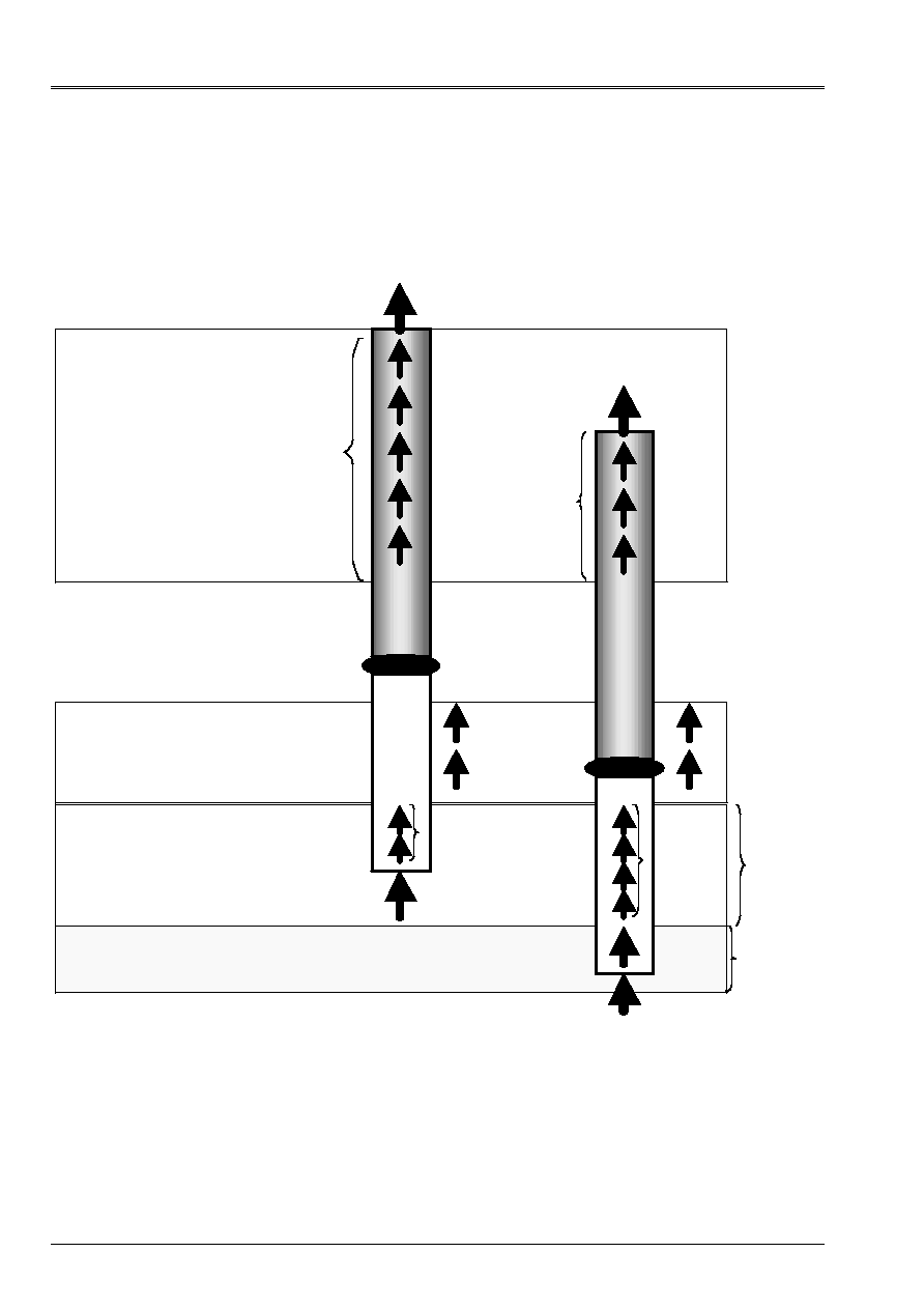
Code_Aster
®
Version
8.2
Titrate:
Operators
AFFE_CHAR_MECA
and
AFFE_CHAR_MECA_F
Date:
22/02/06
Author (S):
X. DESROCHES
Key
:
U4.44.01-I1
Page
:
92/92
Instruction manual
U4.4- booklet: Modeling
HT-62/06/004/A
4.49.4 Position of the points of application of the forces
Area 1: mechanism of lifting
Area 2: continuous guidance
Area 3: tube guide/dahpot
Zon E 1:
F
PMEC =
force
pon ctu it in
high of the stem of
order
F
MEC =
force
distributed on
stem of
order
Zon E 2: F
plaq =
distributed on G cont
Zon E 3:
F
TG =
force distributed on the pencil
absorbent
F
TG =
force p onctuelle in bottom of
absorbing pencil
Before
hammering
After
hammering
FPMEC
FPMEC
FMEC
FMEC
FPLAQ
FPLAQ
FTG
FPTG
FTG
FTG '
FPTG '