|
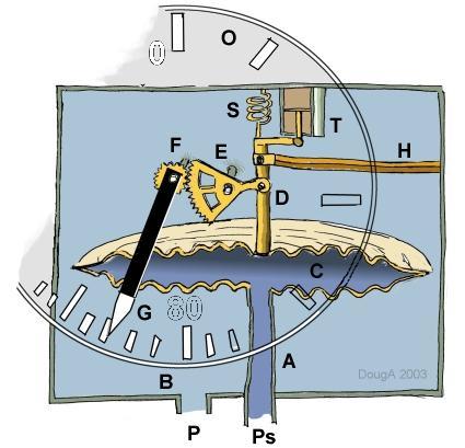
Pressure from the static port (P) enters the instrument (B) and surrounds the cannister (C). Pressure from the pitot port (Ps) enters via tube (A) inside the cannister (C). The difference between stagnation and static pressure is dynamic pressure which is proportional to velocity squared. The pressure difference will expand the cannister (C) moving rod (D) hence rotating gears (E) and (F) to give an angular movement of indicator needle. (G). A scale (O) shows typically knots (nautical miles per hour) airspeed and is calibrated by adjustment of spring (S) at manufacture. The angular scale will not be uniform as velocity is indicated whereas dynamic pressure is a measurement of velocity squared. Vibration damping is provided by dashpot (T) and movement in cannister or rod components due to thermal changes is compensated for by a bi-metal system (H). [Back to Instruments Main Page] © AMME,University of Sydney, 2003-06
|

 A
schematic diagram is shown with components to indicate the typical operation
of an airspeed indicator.
A
schematic diagram is shown with components to indicate the typical operation
of an airspeed indicator.