|
The
primary flight instruments of many aircraft rely on direct
measurement of aerodynamic pressure to predict the altitude,
airspeed and climb rate of the aircraft. These instruments use
simple mechanical means to display information to the pilot.
Schematic diagrams and explanations of the working of these
instruments are shown below.
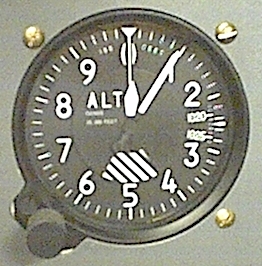
Altimeter
 The
altitude of an aircraft can be obtained by using a measurement of
the static pressure of the surrounding atmosphere. A single
pressure line from the static
port
is all that is required as input for the instrument. Although the
rate of change of pressure with altitude is well known, based on
an International
Standard Atmosphere
model, the ambient sea level pressure at any location of the
earth's surface can vary from day to day due to meteorological
conditions. The instrument will require zeroing before and
sometimes during the flight. This is done by setting the
instrument to the ambient pressure of the airport at the start of
the flight and resetting as required. It is therefore important to
remember that this instrument measures height above sea level and
not height above current ground location. For accuracy of
measurement the instrument usually has at least two sometimes
three indicator needles operating on different scales. For the
instrument shown the larger needle indicates 100's of feet and the
smaller 1000's of feet. Ambient sea level pressure preset value is
shown in the rectangular box on the right (measured
in HectoPascals). Click on the Altimeter
image to view a schematic diagram showing its internal operation. The
altitude of an aircraft can be obtained by using a measurement of
the static pressure of the surrounding atmosphere. A single
pressure line from the static
port
is all that is required as input for the instrument. Although the
rate of change of pressure with altitude is well known, based on
an International
Standard Atmosphere
model, the ambient sea level pressure at any location of the
earth's surface can vary from day to day due to meteorological
conditions. The instrument will require zeroing before and
sometimes during the flight. This is done by setting the
instrument to the ambient pressure of the airport at the start of
the flight and resetting as required. It is therefore important to
remember that this instrument measures height above sea level and
not height above current ground location. For accuracy of
measurement the instrument usually has at least two sometimes
three indicator needles operating on different scales. For the
instrument shown the larger needle indicates 100's of feet and the
smaller 1000's of feet. Ambient sea level pressure preset value is
shown in the rectangular box on the right (measured
in HectoPascals). Click on the Altimeter
image to view a schematic diagram showing its internal operation.
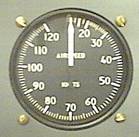
Airspeed
Indicator
 The
airspeed of an aircraft can be obtained from the difference
between atmosphere static pressure and the measured total pressure
from a pitot tube placed in the airflow. The two pressures
required come from lines to the static
port
and an second to the pitot
port.
The difference between these pressures is the dynamic pressure
created by the motion of the vehicle through the air. The
airspeed of an aircraft can be obtained from the difference
between atmosphere static pressure and the measured total pressure
from a pitot tube placed in the airflow. The two pressures
required come from lines to the static
port
and an second to the pitot
port.
The difference between these pressures is the dynamic pressure
created by the motion of the vehicle through the air.

where
V is the velocity of the aircraft and is
the density of the surrounding air. is
the density of the surrounding air.
As the instrument does
not have information on the actual density of the air at the
aircraft's altitude, an assumed standard sea level density is used (1.225
Kg/m3)
under assumed sea level flight conditions. The true airspeed may
be significantly higher as the ambient density at the altitude
will be lower than the sea level value. A correction will need to
be made to calculate true airspeed. At high speed, where the
surrounding air starts to be compressed by the flight of the
vehicle, the assumed sea level standard density will again be
inaccurate and a further correction for compressibility made to
the measurement reading. The instrument only measures speed
relative to the surrounding air so actual ground speed will need
to be calculated based on prevailing wind conditions.
The
instrument shown gives a reading of indicated airspeed in knots
(nautical miles per hour). Click in the image of this instrument
to see a schematic diagram showing its operation.
Vertical
Speed (Climb/Descent Rate)
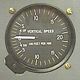
The
vertical speed indicator shows the current rate of climb or
descent of the vehicle in feet per minute. It is feed from a
pressure line from the static port in a
similar fashion to the altimeter. However this instrument does not
measure the absolute pressure but the rate at which the
surrounding static pressure is changing. Its internal metering
system is calibrated to give the rate of change of altitude
equivent to the measured rate of change of pressure.
Click
on the image of this instrument to see a schematic
diagram showing
its internal operation.
Static
Port
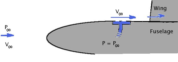
The
pressure of the surrounding atmosphere is obtained through a flush
mounted static port. This is usually located on the side of the
fuselage in a position which will have a local
surface pressure which is closely matching the stream ambient atmospheric
air pressure. The position must be calibrated and not where there is
significant pressure change due to the pressure field of the wings, flow
separations from joins or protrusions on the fuselage, propellor
slipstream or jet wake effects.
Pitot
Port
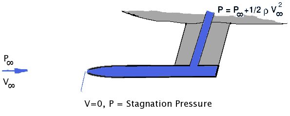
A pitot tube is used to measure the kinetic energy of the airflow due
to the motion of the aircraft. The tube protrudes into the airstream and is
aligned with the flow. The airstream impacting on the open end of the
tube is brought to rest. The pressure at this opening will thus be the sum
of the static pressure of the stream and its dynamic pressure. This is the
total pressure of the flow field.
|