|
Take Off PerformanceTake off performance can be predicted using a simple measure of the acceleration of the aircraft along the runway based on force equilibrium. The forces involved will be, T – Thrust of propulsion system pushing aircraft along runway. D – Aerodynamic Drag of vehicle resisting the aircraft motion. F – Rolling resistance friction due to the contact of wheels or skids on the ground. During take-off run the imbalance in these forces will produce an acceleration along the runway.
where dV/dt is the acceleration along the runway and m is the mass of the vehicle. 1. Rotation Velocity. The procedure for take-off will be that the vehicle will accelerate until it reaches a safe initial flying speed, the pilot can then rotate the vehicle to an attitude to produce climb lift and it will ascend from the ground. The determination of this safe flying speed or rotation speed, VR, is a critical factor in determining take-off performance. For safety reasons VR is usually determined as being 1.2 * VSTALL or 1.1*VMIN CONTROL which ever is greater. Stall speed, VSTALL, is the lowest speed that the aircraft can be flown before the airflow starts to separate from wings as the angle of attack becomes too great. It can be calculated based on knowledge of the aircraft take-off configuration and hence the maximum achievable lift coefficient CL(max). To maintain level flight the lift produced must equal the weight, at the point just before stall this leads to the following balance,
hence stall speed can be calculated as,
Minimum control speed, VMIN CONTROL is a more complex calculation and requires knowledge of the stall characteristics of the tailplane and elevator. For conventional aircraft there is only a small difference between VR calculations based on stall speed or minimum control speed. As well as rotation speed there are other safety considerations as shown in the following figure.
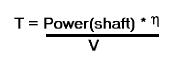
V1- Abort decision speed. Below this speed the take-off can be safely aborted. After this there will not be sufficient runway length to allow the aircraft to decelerate to a stop. V2 – Safe climb speed. Below this speed aircraft cannot attain sufficient climb rate. Aircraft must climb at a minimum gradient to avoid obstacles at the end of the runway. With engine failure on multi-engined aircraft, this speed should still be achievable. 2. Thrust The thrust of gas turbine or turbofan engines will be relatively constant during take-off. A good assumption is to use the manufacturer's values for maximum static thrust for take-off calculations. The thrust of a propeller driven aircraft can be found from the given shaft horsepower data for the engine and the use of the equations using propeller efficiency given in the previous section.
It is critical to correctly estimate the propeller efficiency for the particular aircraft velocity along the runway. At V=0 the efficiency is 0 and at V=VR the efficiency will be in the range 50% to 80% depending on the type of propeller system used. 3. Drag The resistance to motion due to the air viscosity will give a drag of
where CD can be considered constant and calculated using the formula shown in the previous section Section 2. 4. Rolling Resistance The friction between aircraft and runway will be proportional to the normal force exerted by the aircraft on the runway.
The normal force will be the difference between Weight of aircraft and Lift, the friction coefficient will be typically of a magnitude of 0.02 for a standard tarmac runway. 5. Average acceleration and distance to rotation. The rate of change of velocity can be predicted at any point on the take-off roll by substituting results (2),(3) and (4) into equation (1). The subsequent velocity can be found by integrating this result and the distance traveled found by integrating the velocity.
A typical acceleration will be dominated by the drag component as thrust, weight and friction are relatively constant during this period. This leads to the result shown where acceleration is inversely proportional to velocity2.
Due
to the quadratic nature of acceleration change, an average value,
This means
6. Take-Off (Balanced) Field Length. The required length of runway will be the sum of the distance required to get to rotation speed and the extra length required to allow for rapid braking if the pilot decides to abort take-off at the decision speed V1. This length will typically be considerably longer than the distance required to achieve flying speed.
Distance to V1 can be calculated in a manner similar to that shown for VR. The calculation of braking distance will require knowledge of the maximum braking friction coefficient that can be generated by the aircraft. This information should be available from manufacturer's data. Braking distance calculations should also be done without any assumption of reverse thrust from engines as during a take-off abort, engine power may not be available. © AMME, University of Sydney, 1998-2006. |

 (1)
(1)
 (2)
(2) (3)
(3) (4)
(4)
 for the range of velocities from zero to VR can be
found at the point when
for the range of velocities from zero to VR can be
found at the point when
 .
This average acceleration can be used to simplify calculations and
the take-off run can be assumed to be a constant acceleration for the
time taken to get from 0 to VR.
.
This average acceleration can be used to simplify calculations and
the take-off run can be assumed to be a constant acceleration for the
time taken to get from 0 to VR. and
and
 where t is time from start to point where VR
is attained. Rearranging leads to a relatively simple calculation to
predict take-off distance.
where t is time from start to point where VR
is attained. Rearranging leads to a relatively simple calculation to
predict take-off distance.