Contact stresses
We have seen how contact stresses may be treated approximately under the heading of 'bearing' or 'crushing', using the concept of projected area. We now examine these stresses in more detail.
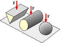
In the contact between theoretically rigid bodies such as the plane with wedge, cylinder or sphere, stresses are infinite since the contact area is zero.
 In real life however neither the base (b) below nor the cylinder (c) is completely rigid - rather both contacting elements must deform as indicated at (d). Elasticity requires gradual transition of both members from their free boundaries to the common interface area (e).
These last sketches are of course grossly exaggerated - contact areas between metal components are small but non-zero, and give rise to stresses which are finite but large.
It is possible to analyse certain simple contacting body geometries - simple in that end effects are ignored for example. The analysis is still complex, so we shall quote rather than derive the results in order to obtain an appreciation of the behaviour for common geometries.
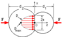
Shown are two spheres, or cylinders of length L in end view, with greatly exaggerated deflections. A Cartesian system is defined with the y-axis normal to the sketch plane. Both components deform; the generally non-plane contact area extends a distance 'a' from the z-axis of symmetry, and the contact pressure and loading severity are maxima on this axis.
The equivalent modulus E* and the equivalent diameter d* are defined by :
1/E* = 1/E'1 + 1/E'2 where E' = E/( 1-ν2 )
1/d* = 1/d1 + 1/d2 where |d2| >|d1| and is negative if internal.
The principal compressive stresses are then given by Shigley (op cit) :
| ( 5a) Spheres
|
|
| Contact zone size
| a3
| =
| 3 F d* / 8 E*
|
|
| Maximum contact pressure
| pmax
| =
| 3 F / 2 π a2
|
|
| Normalised principal stresses
| sx
| =
| sy = ( 1 + ν )( 1 - φ arccot φ ) - 1/( 2 ( 1 + φ2 ))
|
|
| ( s = σ/pmax @ φ = z/a )
| sz
| =
| 1/( 1 +φ2 )
|
| ( 5b) Cylinders
|
|
| Contact zone size
| a2
| =
| 2 F d* / π E* L ; L is the cylinders' contact length
|
|
| Maximum contact pressure
| pmax
| =
| 2 F / π a L
|
|
| Normalised principal stresses
| sx
| =
| 2 ν ( √( 1 + φ2 ) - φ ) ; sz = 1/ √( 1 + φ2 )
|
|
| ( s = σ/pmax @ φ = z/a )
| sy
| =
| √( 1 + φ2 ) ( 2 - 1/( 1 + φ2 )) - 2 φ
|
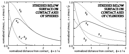
These stress ratios are plotted for Poisson's ratio ν = 0.3, together with the equivalent stress from the distortion energy failure theory. Evidently for both spheres and cylinders the maximum equivalent stress occurs just below the surface and may be taken to be 60% of the peak pressure.
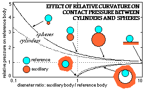 Stresses are proportional to the peak contact pressure, which in turn depends on the relative size of the two bodies. If a reference body (cylinder or sphere) is contacted by an auxiliary body whose diameter varies (with other parameters constant) then the peak pressure will change as shown. The advantage of close conformity in reducing stress levels is apparent - ball bearings capitalise on this by using toroidal rather than cylindrical race surfaces.
EXAMPLE
Ascertain the peak pressure between a flat cast iron surface and a 100 mm diameter steel wheel, 5 mm wide and carrying a load of 500 N. If the cast iron's compressive ultimate is 750 MPa and the steel's yield is 350 MPa, estimate the factor of safety.
E'1 = [ E/( 1 - ν2 ) ]1 = 207/( 1 - 0.292 ) = 226 GPa d1 = 100 mm
E'2 = [ E/( 1 - ν2 ) ]2 = 100/( 1 - 0.212 ) = 105 GPa d2 = ∞
E* = 1/( 1/E'1 + 1/E'2 ) = 1/( 1/226 + 1/105 ) = 71.7 GPa d* = 100 mm
Then, from the cylindrical equations ( 5b) with L = 5 mm :
a2 = 2 Fd* / π E* L = 2 x 500 x 100 / π x 71.7E3 x 5 whence a = 0.30 mm
pmax = 2F / π a L = 2 x 500 / π x 0.30 x 5 = 213 MPa
It will be recalled that a safety factor is essentially a load criterion - it is a stress criterion only when stress is proportional to load, which is NOT the case here. From the above pmax ∝ F /a where a ∝ √F, so that pmax ∝ √F.
For the steel, the 500 N load gives rise to a maximum equivalent stress of 0.6 pmax = 128 MPa, so the load necessary to produce yield will be 500 (350/128)2 = 3740 N. That is, the steel's safety factor is 3740/500 = 7.5.
Cast iron failure will occur when the maximum pressure, ie. the maximum surface compressive stress, reaches the compressive ultimate. Now the 500 N load above gives rise to pmax of 213 MPa, so the load necessary to induce fracture will be 500 (750/213)2 = 6200 N. That is, the cast iron's safety factor is 6200/500 = 12.4.
The overall factor of safety is therefore : minimum( 7.5, 12.4) = 7.5
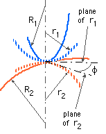
The general case in which two contacting bodies 1 & 2 are each curved three-dimensionally is too complicated for closed-form evaluation of the stresses. Young (op cit) presents a numerical solution for the maximum contact pressure which may be approximated as a guide to safety. The minimum and maximum radii of curvature at the point of contact are r1 and R1 for body 1, and r2 and R2 for body 2. The reciprocals 1/r1 and 1/R1 are known as the principal curvatures of body 1, and 1/r2 and 1/R2 of body 2, and in each body the principal curvatures are mutually perpendicular. The plane containing curvature 1/r1 in body 1 makes an angle φ with the plane containing curvature 1/r2 in body 2.
The equivalent curvature radius r* and the parameter λ are defined by :
1/r* = 1/r1 + 1/R1 + 1/r2 + 1/R2
λ2 = (2/π) arccos { r* √ [ ( 1/r1 - 1/R1 )2 + ( 1/r2 - 1/R2 )2 + 2( 1/r1 - 1/R1 )( 1/r2 - 1/R2 ).cos 2φ ] }
Then, for λ > 0, the elliptical contact area Ac and the maximum contact pressure pmax are :
( 5c) Ac ≅ π ( 3 Fr*/2λE* )2/3 ; pmax = 3F /2Ac
In the case of ductiles, it is reasonable to take the maximum equivalent stress to be 0.6 pmax analogously to spheres and cylinders, since this figure does not appear to be affected significantly by the geometry. The approximation ( 5c) for the contact area can be 7-8% high, so that the predicted equivalent stress may be underestimated by this percentage.
EXAMPLE
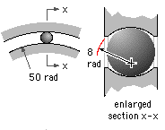
The diameter of a ball in the steel bearing illustrated is 15 mm and the groove radius of both inner and outer races is 8 mm. If a single ball were to transmit the whole radial load of 5 kN, what maximum equivalent stress would result?
Let the ball be body 1 and the inner race body 2. Then r1 = R1 = 7.5 mm; r2 = -8 mm (since concave) and R2 = 50 mm.
From the above r*= 6.19 mm, φ = 0 and so λ = 0.540. Since E*= 114 GPa for steel-on-steel, from ( 5c) Ac = 2.60 mm2, pmax = 2.88 GPa and σ* = 0.6 pmax = 1.73 GPa.
Repeating for the outer race, r1 = R1 = 7.5 mm; r2 = -8 mm and R2 = -65 mm (since concave). From the above r*= 7.92 mm, φ = 0 and so λ = 0.575; from ( 5c) Ac = 2.94 mm2, pmax = 2.55 GPa and σ* = 1.53 GPa.
For the bearing as a whole, the maximum equivalent stress is 1.73 GPa.
 Copyright 1999-2005 Douglas Wright,
doug@mech.uwa.edu.au
last updated May 2005
 Stresses are proportional to the peak contact pressure, which in turn depends on the relative size of the two bodies. If a reference body (cylinder or sphere) is contacted by an auxiliary body whose diameter varies (with other parameters constant) then the peak pressure will change as shown. The advantage of close conformity in reducing stress levels is apparent - ball bearings capitalise on this by using toroidal rather than cylindrical race surfaces.

 In real life however neither the base (b) below nor the cylinder (c) is completely rigid - rather both contacting elements must deform as indicated at (d). Elasticity requires gradual transition of both members from their free boundaries to the common interface area (e).


