The transverse cross-section of a typical prismatic beam is illustrated. It is rectangular with x and y axes chosen parallel to the axes of symmetry of the cross-section, and the z-axis longitudinal to the beam.

|
When the cross-section is not symmetric however - or when it is, and loading planes other than those containing the axes of symmetry are chosen - then coupling between events in orthogonal planes will occur. Thus consider the I- and Z-beams below, each loaded in the y-z plane of the web.

|
We shall adopt a vector approach to examine the stress distribution in general asymmetric bending. A vector here is essentially a vertical list of scalars, shown for compactness by its horizontal transpose ( denoted by ' ) and represented by a boldface symbol. A similar vector approach will be implemented later in the context of fillet welds, however before we delve into vectors, let's recapitulate on how the centroid of a known area is located.

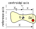
To ascertain the centroidal abscissa ( XG ), an arbitrary reference axis is first set up, from which the position, X, of the general area element δA can be reckoned.
Varignon's Theorem (aka. the Theorem of Moments ) defines XG from :
XG ∫area dA = ∫area X dA
and since the disposition of the area is known, the integrals may be evaluated and XG calculated.
Alternatively, transposing terms to the RHS of the equation, the requirement for G to be the centroid becomes ∫area( X -XG ) dA = 0 or, if the coordinate x = X -XG is reckoned from the centroid, then the centroid must be such that :
( iiia) ∫area x dA = 0
Similar centroidal requirements apply in the y and z directions.
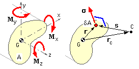
The LH sketch below shows the cross-section of a prismatic beam of known geometry which lies transverse to the longitudinal z-axis of the beam.
 The origin of any convenient Cartesian system is placed at the centroid of the cross-section, G, with the x and y axes lying in the plane of the section. The stress resultant at the cross-section is M = [ Mx My Mz ]' where Mx and My are bending moment components and Mz is a torque - all taken positive by the right hand rule. There is no force resultant in pure bending.
A representative small element of cross-sectional area, δA, is identified at r = [ x y z ]' in the Cartesian system shown in the right hand sketch, where z = 0 here since all cross-sectional area elements lie wholly in the x-y plane. The centroid is defined by :-
( iii) ∫area r δA = 0 - ie. as ( iiia) above, ∫area x.dA = 0; ∫area y.dA = 0; ∫area z.dA = 0
Due to application of the turning effect, M, the cross-section will rotate about some centre of rotation, C, whose position though fixed at rc is not (yet) known. The radius vector from the centre of rotation to δA is
( iv) s = r - rc
This rotation - and correlation of compatibility with the symmetric case - requires that the (small) strain at the element will be orthogonal to and linear in this s-vector. So, presuming elastic behaviour, the stress on δA, σ = [ σx σy σz ]' is also orthogonal to and linear in s, as indicated by the sketch. This may be expressed as :-
( v) s = b x s - const = b x r - c using ( iv),
in which the constant b = [ bx by bz ]' incorporates the necessary linearity while the cross product ensures orthogonality. c = [ cx cy cz ]' is also a constant for all elements in the cross-section under consideration.
Equation ( v) establishes the form of the stress distribution; the two constants b and c may be evaluated from the necessary equivalence of the known stress resultants ( F & M ) and the stress distribution integrated over the cross-section. Thus, since there is no force resultant here :-
F ≡ ∫area s dA = ∫area ( b x r - c ) dA which on integrating by parts
= b x (∫area rdA) - c A ≡ 0
Since this last integral vanishes as a result of ( iii), it is concluded that the constant c also vanishes.
Similarly for the moment resultant :-
M ≡ ∫area r x ( s dA ) = ∫area r x ( b x r ) dA via ( v) with c = 0
Expanding out the triple product and integrating term-by-term leads to :-

|
The constants b and c having been found, the stress at any point r in the cross-section follows immediately from ( v); thus for the case of pure bending where the torque Mz = 0, the vector s degenerates to the scalar σ ( ie. σz ), given by ( v) with ( vi) as :-
( 4) σ = ( ( Mx Iyy + My Ixy ) y - ( Mx Ixy + My Ixx ) x ) / Io2 where Io2 = Ixx Iyy - Ixy2
Some particular cases of ( 4) include the following :
EXAMPLE
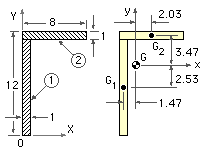
Determine the second area moments of the 12*8*1 cm angle illustrated.
Set up convenient X,Y axes and divide the area into elements (two here) of simple shape whose individual I's can be directly calculated.
 Tabulate, and find first moments of area to define the centroid using (iii).
| δA | X | Y | X.δA | Y.δA | x = X-XG | y = Y-YG | |
| 1 | 11 | 1/2 | 11/2 | 11/2 | 121/2 | -1.47 | -2.53 |
| 2 | 8 | 4 | 23/2 | 32 | 92 | 2.03 | 3.47 |
| total | 19 | 75/2 | 305/2 |
Hence set up centroidal x-y axes, as shown, and calculate :
Ixx = ( 1*113/12 + 1*11 (-2.53)2 ) + ( 8*13/12 + 8*1 (3.47)2 ) = 278.4 cm4
Iyy = ( 11*13/12 + 11*1 (-1.47)2 ) + ( 1*83/12 + 1*8 (2.03)2 ) = 100.3 cm4
Ixy = ( 0 + 1*11 (-2.53) (-1.47) ) + ( 0 + 8*1 (3.47) (2.03) ) = 97.2 cm4
Note that both elements contribute to the product second moment since their centroids lie in the first and third quadrants and hence δA.x.y is positive for both.
Asymmetric bending may be tackled also by resolution of the loading into the principal area senses. The minimum principal axis passes close to the centroids of the area elements.