Some elementary load building blocks were reviewed in the previous chapter 'Stress, Strength and Safety'; readers should be familiar also with the theory of straight beams including energy methods, shear flow and shear centre.
This theorem is a useful tool for determining displacements of an elastic system. The theorem states that the displacement δG at/of any load G acting upon such a system is given by :
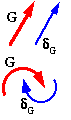
The load G may be a translational force in which case the displacement δG is linear; alternatively the load G may be a rotational moment or torque in which case the displacement δG also is rotational. The displacement and the load are reckoned positive in the same sense - eg. NNE or clockwise as shown.
For a system in which bending strain only is significant, that is for a beam-system :
δG = ∂/∂G [ ∫length ( M2/2EI ) ds ] or, changing the order of operations
( ii) δG = ∫length M/EI.∂M/∂G .ds where s is the distance along the beam.
The deflection under a particular load is thus found by expressing M (and EI if it's not constant) algebraically in terms of distance along the beam, s, then applying ( ii). A couple of examples follow showing this applied to straight beams, however Castigliano comes into his own when the deflections of curved beams are sought.
 EXAMPLE
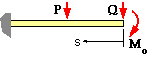
Use Castigliano in bending ( ii) with Q as the load and EI constant :
δG = ∂U/∂Q = 1/EI ∫0L M ∂M/∂Q ds where M = function(s)
There are two spans, ie. two regions of integration. From a free body of each, the bending moment may be found in terms of the known external loads :
(a) M = Qs ; ∂M/∂Q = s ; 0 <= s <= L/2
(b) M = Qs + P( s - L/2) ; ∂M/∂Q = s ; L/2 <= s <= L
So EI δQ = ∫0L/2 Qs.s ds + ∫L/2L [ Qs + P( s - L/2) ].s ds = ( Q/3 + 5P/48 ) L3
The displacement of the cantilever under the load Q is therefore ( Q/3 + 5P/48 ) L3/EI
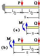
If a displacement is needed for which there is no corresponding actual load, then a fictitious dummy load must be applied to the system. The value of such a dummy load is zero, but it must be included algebraicallly in order to deduce partial derivatives ( for use in ( ii) ) - for although a dummy load is actually zero, partial derivatives involving it generally are not zero. Once these partial derivatives have been ascertained, the dummy load is set to zero when working out the integral in ( ii).
Since the rotational displacement of the end at Q is required here, the dummy rotational load Mo is defined at that end as shown. This external moment will appear on each of the free bodies of the previous example, so that the bending moments at s become :
(a) M = Mo + Qs ; ∂M/∂Mo = 1 ; 0 <= s <= L/2
(b) M = Mo + Qs + P( s - L/2) ; ∂M/∂Mo= 1 ; L/2 <= s <= L
Having evaluated the partial derivative of the bending moments with respect to the dummy load, the dummy load is zeroed in the energy integral. So, with Mo = 0 :
δMo = ∂U/∂Mo = 1/EI ∫0L M ∂M/∂Mo ds
Do not confuse the bending moment M with the external load Mo
So EI δMo = ∫0L/2 Qs.1 ds + ∫L/2L [ Qs + P( s - L/2) ].1 ds = ( Q/2 + P/8 ) L2
The slope of the cantilever at the load Q is therefore ( Q/2 + P/8 ) L2/EI
Many practical beams are curved rather than straight. We consider only beams in the form of circular arcs in the loading plane, with cross-sections symmetric about that plane. These beams may be subdivided into two categories :
 A thick curved beam is characterised by a beam depth which is of the same order as the radius of curvature and so stresses are non-linear, increasing towards the inside of the bend where curvature effects are more pronounced. We examine this stress concentration later, however let's first look at thin curved beams.
A thin curved beam is typified by the quadrantal cantilever illustrated. Its radius is R and it is subjected to two components of end load, V & H. The loaded end's deflection is sought.
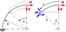
Castigliano's theorem may be applied directly, although the angle θ is usually a more convenient independent variable than the distance s when it comes to curved beams. Thus in the sketch, at the general free body's cut end defined by θ, the bending moment required for equilibrium is :
M = HR ( 1 - cosθ ) + VR sinθ.
The strain energy of direct tensile and shear forces is negligible in the presence of bending, so the forces need not be evaluated.
Clearly in ( ii) s = Rθ so that all terms are functions of θ, enabling the integral to be evaluated.
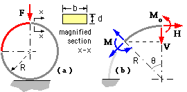
A proving ring of radius R and rectangular cross-section b*d is subjected to a force, F, as shown. The elastic modulus and design stress of the material are E and S respectively. Determine :
- the ring deflection under the load,
- ditto, transverse to the load, and
- the maximum allowable load on the ring.
Consider only one quadrant since the system is symmetric - say the top left quadrant. This is modelled as a cantilever ( which automatically preserves the lower end vertical ) and loaded with -
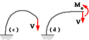 an external moment, Mo. This is not a dummy load. If there were no moment at the end then the end would rotate as shown at (c). But the end remains horizontal due to symmetry of the complete ring, so there must be a moment Mo exerted by the RH mirror quadrant to ensure compatibility δMo = 0 as shown at (d).
Inserting these into ( ii) with EI constant gives the various deflection components as :-
δV = 1/EI ∫0L M ∂M/∂V ds = 1/EI ∫0π/2( VRsinθ - Mo).Rsinθ.R dθ = (π/4VR - Mo) R2/EI
δH = 1/EI ∫0L M ∂M/∂H ds = 1/EI ∫0π/2( VRsinθ - Mo).R(1-cosθ).R dθ = ( VR/2 - (π/2-1)Mo) R2/EI
δMo = 1/EI ∫0L M ∂M/∂Mods = 1/EI ∫0π/2( VRsinθ - Mo).(-1).R dθ = (-VR + π/2 Mo) R/EI
But there is no end rotation, so setting δMo = 0 in the last equation resolves the indeterminacy, giving Mo = 2/πVR.
Substituting this value of Mo into the first two equations gives : δV = (π/4 - 2/π) VR3/EI and δH = (2/π -1/2) VR3/EI.
So, for the complete ring, since V = F/2 then :
diametral deflection, coaxial with load = 2 δV = (π/4 - 2/π) FR3/EI
diametral deflection, transverse to load = 2 δH = (2/π - 1/2 ) FR3/EI.
From the bending moment equation above, the maximum moment occurs at θ = 0 and is Mmax = Mo = 2/πVR from above.
Since bending is the only significant load building block, the maximum stress is
σ = Mmax ymax/I = (2/πVR )( d/2 ) /( bd3/12 ).
The maximum allowable load on the ring occurs when σ reaches the design stress, S, and is therefore Fmax = πbd2S / 6R.