EXAMPLE
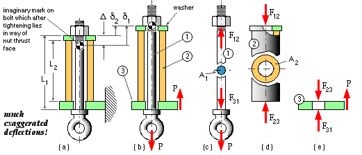
An eyebolt 1 and tubular sleeve 2 are supported by the plate 3 as in (a), (b) below.
Initially the nut is just finger tight ( 'snubbed' - there are no gaps in, and no appreciable loads on the assembly).
Subsequently the nut is tightened by screwing it a known distance Δ along the thread, then the temperature of the sleeve only is increased by t, and finally the load P is suspended from the eye.
Given the axial stiffnesses k1 and k2, resolve the indeterminacy in the final loaded state.

|
( i) δ1 - δ2 = Δ
Free bodies of the separate components are now prepared - (c), (d), (e) - in which the unknown action/reaction at each contact is identified conveniently by the indices of the two components in contact. No components are stuck together so the action/reactions must be 'pushes' on the contacting components - hence F12 is shown in free body (c) pushing on component 1, and on free body (d) pushing on component 2. This force is the resultant of (presumably uniform) pressure over the annular contact area - the washer's purpose is to distribute this pressure evenly.
There are three contacts 1-2, 2-3, 3-1 between the three components, hence the three contact resultants F12, F23, F31 appear on the three free bodies. Equilibrium of all three free bodies requires that :-
( ii) F12 - F31 = P
( iii) F12 = F23
It is noted particularly from the free bodies (c), (d) that :
Eyebolt 1 From above, the eyebolt is subjected to a tensile load F12 and suffers a tensile deformation δ1, so the constitutive law ( 2a) consistent with compatibility, equilibrium and constant temperature is :-
( iv) δ1 = F12 / k1 ; k1 = ( A E / L )1
Sleeve 2 From above, the sleeve is subjected to a compressive load F12 and a temperature rise t, and suffers a tensile deformation δ2, so by inspection or by adhering to a positive tensile convention, the form of ( 2a) consistent with compatibility, equilibrium and temperature rise of this component is :-
( v) δ2 = - F12 / k2 + L2α2t ; k2 = ( A E / L )2
( vi) F12 = Fo where the known initial load is defined as Fo = ke ( Δ + L2α2t )
in which the equivalent series stiffness ke is given by 1/ke = 1/k1 + 1/k2
Fo is called the initial load because it is due to nut tightening and heating before the external load P is applied.
This result seems ridiculous since it has F12 (the only failure agent in both 1 and 2) completely independent of the applied load P - ie. the load may be raised out-of-hand with no adverse effects on bolt or sleeve !!!
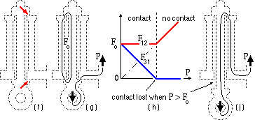
The channel for the flow analogy is shown at (f) here; the restrictive annular areas are arrowed.
 Two distinct force paths are suggested in (g) - that of P from the eye directly into the support and byepassing the bolt shank and sleeve, and that of the self-equilibrating initial load Fo in the bolt shank and sleeve. These make physical sense as no external support is necessary to cater for a temperature rise of the sleeve or for a tightening of the nut - these effects, embodied in Fo, are resisted internally in the assemblage. Note that the force paths have been greatly simplified here to avoid confusion in the sketch.
The two forces F12 and F31 are graphed against increasing external load P in (h).
F12 is constant at Fo from ( vi) while from ( ii) F31 drops off from this value in proportion to P, until it becomes zero when P reaches a value of Fo. But F31 is the force between eyebolt and support; it cannot be negative (there is no adhesive to enable the eyebolt to pull down on the support). The physical interpretation of F31 reaching zero is that contact between eyebolt and support is lost as indicated by ( j).
This then is the reason for the apparent anomaly in the foregoing analysis. The analysis is perfectly correct - but only within the limitations of its assumption, implicit in the free bodies (c) and (e), that contact between 1 and 3 is maintained and F31 > 0.
This assumption should not be confused with the unrelated deformation assumption of (b).
If it is desired to increase the load P at which contact is lost, then (h) indicates that Fo must be raised, probably by further nut tightening, Δ. After contact is lost (P > Fo) the arrangement is statically determinate and component loads can be found immediately from equilibrium only. Setting F31 = 0 and F12 = P in the free bodies (c), (d) and (e) demonstrates that all components transmit the external load P. This is confirmed physically by the force path ( j).
Having found the force F12 transmitted through the bolt eg. the bolt's safety can be assessed from the tensile design equation ( 1b) applied to the component 1 :
n1 = (AS/P)1 = Ac1S1/F 12 ; F12 = maximum( P, Fo) from (h).