
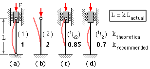
 An ideal column is perfectly straight initially, supported by pinned ends which are constrained to move axially, and loaded by a coaxial compressive force F as shown in sketch ( a).
The behaviour of an ideal column having a particular slenderness is illustrated at left below. The load may be increased undramatically until it reaches the Euler stability limit Fc whereupon deflections instantaneously increase out of hand and the column collapses. This instability is geometric in nature and unlike yielding or fracture has got little to do with material - for example a cardboard tube can sustain a higher compressive load than a steel wire.

|
Historically, columns have been classed as either :
| short | - | which fail when the strength limit S is reached (a material criterion), or |
| long | - | which fail when the stability limit σc is reached (a geometric criterion) |
| . . . often described by empirical design equations such as the 'parabolic' or 'JB Johnson' formulae. | ||
Perfect columns, like perfect mechanisms, are theoretical idealities. Imperfections must arise in practice - and the effect of these is invariably to reduce the load carrying capacity predicted by elementary idealised theory. We examine a practical column whose imperfections prior to load application may be modelled by either of the two arrangements illustrated below, in which the imperfection is characterised by the maximum eccentricity emax.

|
Imperfect columns are not unlike beams in that bending is a major failure mechanism, however there are two significant differences between columns and beams :-
|
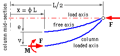
A horizontal column is symmetric about its midsection x = 0.
A free body of its right hand end is shown, with boundary at x = φL where -1/2 ≤ φ ≤ 1/2. The stress resultant at the free body's LH boundary consists of the axial force, F ( which equals the column load ) and the bending moment, M. The eccentricity of the unloaded column axis from the load's line of action is e - the relationship between e and x will depend upon the form of initial imperfection which exists. Three different configurations, each characterised by maximum eccentricity emax, are examined in parallel :
| Configuration : | straight; offset load | bent parabolically | bent sinusoidally | ||||
| ( a) | e at φ | = | emax (constant) | emax ( 1 - 4φ2 ) | emax cos πφ | ||
| For equilibrium of the free body, in which v is the additional deflection at φ when the load F is applied | |||||||
| ( b) | M = F ( e + v ) and = - EI d2v/dx2 from bending theory. | ||||||
| Equating these right hand sides, substituting x = φL and noting that FL2/EI = π2 ψ where ψ is a constant common to all cross-sections, yields | |||||||
| ( c) | d2v/dφ2 + π2 ψ v = - π2 ψ e whose solution is of the form | ||||||
| ( d) | v = C cos( π√ψ.φ ) + D sin( π√ψ.φ ) + particular integral | ||||||
| . . . in which C and D are integration constants, and the particular integral refers to the relevant equation ( a) for e on the RHS of ( c). The integration constant D must vanish by symmetry about φ = 0, and C must satisfy zero deflection at the ends ( v=0 at φ=±1/2 ).
Inserting these boundary conditions, the elastic curves for the three cases are | |||||||
| ( e) | v / emax | = | sec(π/2√ψ) cos(π√ψ.φ) - 1 | 8/π2ψ sec(π/2√ψ) cos(π√ψ.φ)
- 1 - 8/π2 ψ + 4φ2 | [ ψ/(1-ψ)] cos π φ | ||
| The relevant maximum deflection at the centre of the column, φ = 0, follows as | |||||||
| ( f) | vmax /emax | = | sec(π/2√ψ) - 1 | 8/π2 ψ [ sec(π/2√ψ) - 1 ] - 1 | ψ/(1-ψ) | ||
| The maximum compressive stress, on the concave face of the column at φ = 0 is | |||||||
| ( g) | σmax = σdirect + σbending max - which with ( b) becomes
= σd + F ( emax + vmax ) ymax / Iz - or, normalising by σd 1/θ = 1 + η ( vmax /emax + 1 ) Substituting the appropriate ratio vmax /emax from ( f) into this last gives the desired relationships for the three cases | ||||||
| ( h) | 1/θ | = | 1 + η sec(π/2√ψ) | 1 + η 8/π2 ψ [ sec(π/2√ψ) - 1 ] | 1 + η / ( 1 - ψ) | ||
| . . . where θ = σd /σmax , ψ = σd /σc and both θ, ψ ≤ 1. | |||||||
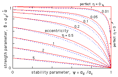
The full red loci refer to both the initially bent columns - there is no difference distinguishable at the scale of the graphs between parabolic and sinusoidal imperfections. This reinforces the previous conclusion that an imperfection's actual form is of lesser significance than its magnitude. It is justifiable therefore to adopt the simplest equation here - for the column initially bent sinusoidally - to represent all forms of imperfection. This also has the great advantage of enabling closed form solutions. So, substituting for ψ, θ in the rightmost equation ( h)
( j) ( σmax - σd ) ( σc - σd ) = η σd σc ; σd ≤ σc, σmax
from which the maximum stress σmax may be found for a given load (implicit in the direct stress σd) acting on an imperfect column which is characterised by a certain critical Euler stress σc and eccentricity ratio η.
If the load safety factor, n, corresponds to a certain actual load, F, then the direct stress at failure, σd = Ffailure /A = n F/A, corresponds to σmax reaching the material's compressive strength, S. Application of ( j) to this failure situation yields the design equation :-
( 2) σd2 - σd [ S + ( 1 + η ) σc ] + S σc = 0 ; σd = n F/A ≤ σc , S
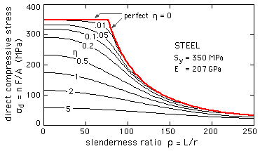 The direct stress from ( 2) is plotted here for a particular steel. The graph demonstrates the generality that the larger the imperfections, the smaller the load capacity.
The intercepts on the direct stress axis are S/( 1+η ), since for a short squat column ρ --> 0, instability tendencies are negligible, σc --> ∞, and so the intercepts follow from ( 2) or more immediately from the sketch of the short column below.

If the column is brittle then the tensile stress on the convex side, evaluated along the lines of ( g), may be more significant than the larger compressive stress which must be the more critical peak for ductiles.
Various proposals ( based upon observations of course ) have appeared in the literature, however the recommendations of the Steel Structures Code will be adopted here. This Code implements equation ( 2) with a safety factor of 5/3, and stipulates that :
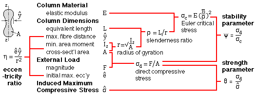
( k) η ∝ ρ2 = 3 E-5 ∗ ρ2 = 3 E-5 ( π2 E/σc ) and = ση /σc
. . . . where the equivalent imperfection stress ση ≡ 3 E-5 π2 E is evidently a material characteristic, say 60 MPa for steel. A lower value is probably permissible for small non-critical components in mechanical engineering.
Equations ( 2) and ( k) lead to the more useful design equation applicable to nominally perfect columns, namely :-
( 3) σd2 - σd ( S + σc + ση ) + S σc = 0 ; σd = n F/A ≤ σc , S
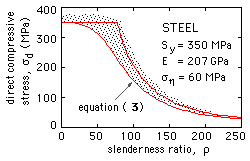 The direct stress at failure ( n = 1) according to this equation, forms a lower bound to experimental results from tests on ostensibly perfect columns. The scatter of these results is due to a number of causes which the foregoing treatment neglects, among which are plastic behaviour, non-ideal supports, buckling mode interaction (especially local buckling) and residual stresses.
Residual stresses arise when a complex section cools differentially after manufacture by hot rolling, forging, welding, etc. and may typically reach 30-40% of yield. They are thus far from negligible, and heat treatment aimed at reducing them is usually impracticable, for structural sections at least. They may be partially allowed for when applying the above theory, by reducing the design yield strength accordingly.
The causes of scatter may be regarded as equivalent imperfections, and the Code's recommendations are presumably based on this all-embracing view.