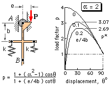
As noted, the buckling propensities of a system are reflected in the shape of the equilibrium path, ie. the load- deflection curve. If a system is in equilibrium then its total potential energy, U, has a turning value since an infinitessimal disturbance, dδ, of the system from its equilibrium position does not change the potential energy (PE) - δ is any convenient characterising displacement. Expressed mathematically, the equilibrium path is thus defined by :

( 1a) U' ≡ dU/dδ = 0
The type of equilibrium which exists at any point on the path - stable, neutral or unstable - is also an important consideration; it may be deduced by taking the second derivative :-
| ( 1b) U" ≡ d2U/dδ2 | > 0 ; PE - minimum stable equilibrium |
| = 0 ; PE - zero slope neutral equilibrium | |
| < 0 ; PE - maximum unstable equilibrium |
Perfect structures are figments of the imagination. If the mechanism above were manufactured, it would be impossible to ensure that initially A, B, and C all lay on the load's line of action, or that both springs were completely free before the load was applied.


With the gradual depletion of easily exploitable gas and oil fields, less accessible sub-sea reserves are being increasingly tapped. The distribution pipework of these often lie at depths of around 200 m and is thus subjected to substantial external pressures. It is imperative
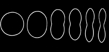
 that pipe buckling is prevented as it propagates catastrophically, being driven by a longitudinal component of the water pressure at the speed of sound in the metal wall. Cross- sections taken from various positions along a partially collapsed pipe are shown on the left here.
The minimum pressure which maintains buckle travel in a particular pipe is the critical propagation pressure, pc for the pipe, and we turn now to the prediction of this 'buckling load.'
The buckled shape indicates gross plastic deformation - indeed elastic effects pale into insignificance and the pipe material assumed to be perfectly plastic, with yield strength Sy. As a result of this non-conservatism, the energy methods of the previous sections cannot be used; however work-energy principles are applicable.

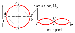
The adopted model consists of unit length of the thin pipe ( t/D --> 0 ) illustrated here, with four plastic hinges - a, b, c and d. Deformation occurs only at the hinges, so the four lobes of the cross- section rotate about the hinges without otherwise deforming, thus forming the collapsed shape a', b', c', d'.
The material at a plastic hinge is taken to be perfectly plastic - ie. stresses can only be either zero or yield as shown at ( i) below. If pure bending
 occurs across the thickness t then tensile yield extends across half the thickness ( ii) and compressive yield extends across the remaining half thickness. The resultant ( iii) of each stress block is a force Sy t/2 ( per unit length). The hinge therefore develops a constant bending moment My = Sy t2 /4 per unit length as collapse proceeds ( iv).
The work-energy principle may now be applied to the propagation pressure collapsing the plastic hinged model.
Work done by external propagation pressure :
= pressure ∗ change in volume ; or, per unit length :
= pc ∗ decrease in cross- sectional area = pc ∗ square area a-b-c-d = pc D2 /2
Strain energy gain of the four plastic hinges, per unit length :
= 4 My ∗ rotation of each hinge over the process = Sy t2 ∗ π/2
Equating work and energy leads to an estimate of the propagation pressure :
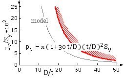
pc = π ( t/D )2 Sy

The model underestimates the propagation pressure mainly because it neglects strain- hardening and the finite extent of the plastic hinges - this last may be appreciated by comparing the actual buckled shape with the collapsed model. A more realistic empirical expression fitted to experimental results is shown; this tends to the model as t/D --> 0.
The ability of this simple model (without empiricisms) to provide a ball park estimate of the collapse load should be appreciated.