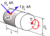
 A common application of compound cylinders is in torque transmission between a shaft and the hub of a pulley or sprocket through an interference fit or a proprietary radially- expanding coupler. The principle of torque transfer may be appreciated from the sketch which shows an element δA of the contact area π DcL, on which the contact pressure, pc, is assumed to be uniform. The maximum torque capacity of the element, δT, may be ascertained if it is assumed that friction breakaway is imminent, whereupon δT = ( f pc δA ) Dc /2 where f is the coefficient of friction. The torque capacity T of the whole joint is therefore :
( xii) T = ΣA δT = π f pc Dc2 L / 2
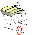
It should be realised however, that this is only approximate as the stress-strain state is much more complex than that on which ( 4) is based. The axial cross-section of a coupling illustrates that torque transfer is gradual along the length of the interface. This implies that the torsional shear stress, τat, varies with the axial coordinate z, in addition to the radial variation. Furthermore, the shear component, τrt, must vary through the wall of each member, and the radial direction is no longer principal.
 At the free surface of each member τrt must be zero, and at the interface it must equal the friction force developed (which will not necessarily correspond to friction breakaway, ie. π f pc δA). Geometric compatibility must therefore be examined - that is equality of the integrated angular displacements of the members at the interface - which in turn depends upon the relative torsional stiffnesses. The coupling is a rotational analogue of the indeterminate tensile connector examined in an earlier chapter.
These considerations lead to the conclusion that interface pressure, stresses and strains all vary in the axial direction, and this, in conjunction with the presence of both τat and τrt, renders the problem essentially three- dimensional and too complex for analysis at this stage. In practice, the situation is usually further complicated by bending stresses, which, being circumferentially asymmetric, lead to fatigue. Shaft design Codes cater for these complexities by means of factors which are based upon experimental findings and experience.
It is possible to carry out a limited analysis however, if the axial variations noted above and the shear component, τrt, are all presumed negligible - in which case the elastic superposition of constant contact pressure and constant torque loadings is feasible. The torsional shear stress at some location in the wall is :
( xiii) τat = Tr/J = τv γ1/2 in which the constant τv is defined as 16 T / π Di3 ( γo2 - 1 )
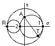
The Mohr's circles will be as indicated, the normal stress components being given by ( 3) and open cylinders presumed. It is evident that the radial direction is principal and that resolution in the a-t plane is possible, yielding the principals :
σ1,2 = σt /2 ± [ ( σt /2 )2 + τat2 ]1/2 ; σ3 = σr
Employing the distortion energy theory for example, and expanding these principals via ( 3) and ( xiii), leads to an expression for the equivalent stress :
σe2 = σm2 + 3 [ ( σv / γ )2 + τv2 γ ]
It may be shown that, if any turning value of σe exists in the wall ( 1 <= γ <= γo ), then it must be a minimum. The maximum equivalent stress, σ*, must therefore occur either at the inner surface ( γ = 1 ) when pressure effects prevail, or at the external surface ( γ = γo ) when torsional effects are dominant. Hence the design equation is :
( xiv) σ*2 = σm2 + 3 . max [ σv2 + τv2 , ( σv/γo )2 + τv2γo ]
This concludes our look at cylinder theory - it enables the design of shaft bushes and hubs, and of compound highly pressurised containers for example. However by far the most common application of cylinders is for simple internally pressurised pipes and pressure vessels - the next element on our agenda.