Cylinder strains are of fundamental importance when resolving statically indeterminate assemblages of cylinders such as compound cylinders. Normal strain components are related to normal stress components through the elastic three-dimensional constitutive law. Thus, from ( 3)
( x) εt = [
σt - ν ( σr + σa ) ] / E = [ ( 1 - ν ) σm - νσa + ( 1 + ν ) σv / γ ] / E
εr = [
σr - ν ( σa + σt ) ] / E = [ ( 1 - ν ) σm - νσa - ( 1 + ν ) σv / γ ] / E
εa = [
σa - ν ( σt + σr ) ] / E = ( σa - 2 ν σm ) / E ie. γ-independent as Lamé requires.
If temperature effects occur then α.δT must be added to each strain component.

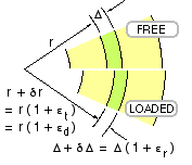
The physical interpretation of εr and εt is shown in the sketch, in which εr = δΔ / Δ is the radial component of strain.
When a cylinder is loaded, we are interested in how it 'breathes' - how its diameter changes as pressures are varied. This is measured by the diametral strain, εd. Circumference is always proportional to diameter, therefore circumferential strain (which is just the tangential strain component, εt ) is always identical to diametral strain - so from ( x)
( xi) εd = δD / D = εt = [ ( 1 - ν ) σm - νσa + ( 1 + ν ) σv / γ ] / E
Note the distinction between the rather confusing terminology here - diametral strain is the strain of a diameter, but radial strain is NOT the strain of a radius, it is merely the component of strain in the radial direction, as noted above.
Thick cylinders use material very inefficiently - referring to the cylinder whose stresses are plotted above for example, the material at the outer surface is stressed only to 1/9 of that at the bore. Assuming, as is commonly the case, that the tangential stress at the bore is tensile in service, this objection may be overcome by providing a residual compressive stress at the bore prior to putting the cylinder into service. Autofrettage is a process, the last in manufacture, in which a controlled internal pressure is applied, high enough to yield the material adjacent to the bore. When this pressure is subsequently removed, a permanent tensile set exists around the bore which is resisted by the surrounding elastic material - with the result that the bore material is in compression. The net tensile stress when the cylinder is eventually put into service is therefore reduced.
Shot-peening, used for establishing a compressive stress in the surface layers of a shaft for example, is generally unsuited to cylinders since the effect is too surface-localised.
 Another method of pre-stressing is to use compound (or composite) cylinders - two or more cylinders which are assembled with an interference fit. The analysis which follows is elastic since the method does not generally involve yielding - and may be applied to sleeves pressed onto shafts, etc.
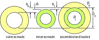
Before safety of either cylinder can be addressed, the common interface pressure pc must be known. But the problem is statically indeterminate since statics reveals only that if pc exists as a contact pressure internal to the outer cylinder, then the inner cylinder is pressurised externally by the same amount. Geometric compatibility and the cylinders' constitutive laws ( xi) must be invoked. If the common diameter Dc increases by δi measured on the inner cylinder as sketched, and by δo measured on the outer, then compatibility requires that :
Δ = δo - δi
Combination of the equilibrium and constitutive considerations proceeds as follows, in which γo, E and ν refer to the appropriate cylinder :-
| INNER | OUTER | |
| internal press. | pi | pc |
| external press. | pc | po |
| σm - eq ( 2) | ( pi - γo pc ) / ( γo - 1 ) | ( pc - γo po ) / ( γo - 1 ) |
| σv - eq ( 2) | ( pi - pc ) γo / ( γo - 1 ) | ( pc - po ) γo / ( γo - 1 ) |
| strain at Dc | at γ = γo | at γ = 1 |
| εd - eq ( xi) | [ ( 1 - ν ) σm + ( 1 + ν ) σv / γo ] / E | [ ( 1 - ν ) σm + ( 1 + ν ) σv ] / E |
| that is | δi/Dc = { 2pi - [(1-ν)γo +1 +ν ] pc } / (γo-1)E | δo/Dc = { [(1+ν)γo +1 -ν ] pc - 2γopo } / (γo-1)E |

|
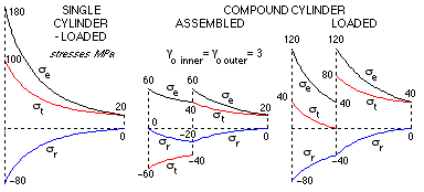
The stresses in a particular compound cylinder are shown,
 after initial assembly and subsequent internal pressurisation. The stresses are significantly lower than those in a single cylinder of the same overall proportions and load. The tangential stress in the inner cylinder is compressive as a result of the as-assembled interference fit, but becomes tensile after the internal pressure is raised to 80 MPa. Quoted equivalent stresses are from the maximum shear stress failure theory.
Note that most texts give an equation for calculating pc only upon initial assembly not after pressurising - such an equation corresponds to ( 4) with the pressures pi and po set to zero.
One particular application of compound cylinders is when the hub of a gear or coupling is shrunk or force- fitted on to a shaft, with subsequent torque transfer between hub and shaft. Solution of this loading must be carried out numerically (by finite elements for example) however we examine now an approximate model of torsional loading of pressurised cylinders to gain some appreciation of real behaviour.