The track for the Potential Energy Propulsion Warman D&B competition involved a false ceiling 3 m above the floor, a 0.5 m square hole in this ceiling, and a target on the floor 7.5 m distant from the hole centre. The task was to transport a can of cool drink from above the ceiling, through the hole to a rest position as close to the target as possible. The sole means of powering the transporter was potential energy. Speed was irrelevant, the competition score being reckoned by the final distance of the can from the target.
It was just natural for Tom and Jerry ( T&J) to form a student design group as they had been close friends for years, living just around the corner from each other. Tom's father operated a machining workshop - Tom had cut his teeth on a lathe and was a competent if unqualified tradesman. Jerry also was experienced in fitting, having worked part-time with Tom's father during vacations.
Like other groups they had six weeks in which to design and build a device - theirs consisted of two major components :
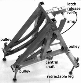 A pulley was mounted atop each leg, and a linear bearing allowed the leg to slide up and down. When any leg was pushed up it turned a common central shaft via a system of pulleys and thick fishing line, the leg travel being retarded by an adjustable disc brake on the shaft.
In operation the cart was mounted at the top of the frame's ramp and retained there by a latch. The assembly was then dropped through the ceiling hole and free fell to the ground where the shock was absorbed by the disc brake. Simultaneously, on contact with the ground the latch was released by an automatic trigger, allowing the cart to roll down the ramp and travel along the ground until brought up short by the unwinding thin fishing line.
Like other groups, T&Jtested their device exhaustively to ensure that Murphy didn't get a look in. However the fiddly manufacture took so long that the device was not finished in time for the event, so the group received no credit for competing.
Undeterred, T&Jwere ready a day or so later to salvage some marks for completing a successful device. The finished model was so beautifully crafted that half the workshop and academic staff turned out to see it through its paces. A few last minute adjustments and at last all was set - the device was released, fell with a resounding crump, leaned gracefully on its side, and sent the cart off at right angles to the track . . . . .
A moment of stunned disbelief before it was realised that one of the shock absorber legs had buckled beyond repair. A disaster! A rerun was out of the question. And this after such extensive testing. Needless to say T&Jwere distraught that the fruits of so much labour came to naught.
The group received very little credit for this. Why? Because the design was far and away too complex - the more bits and pieces there are, the more likely will something go wrong. In this case it was not difficult to predict that there was an outside but still non-zero chance of the device landing awkwardly on one leg so that sliding through the bearing was impossible - behaviour identical to the CompuChamp table sleeves of appendix A which had been brought to the attention of T&J.As an article of craftsmanship the device was excellent; as a design it was a shocker.
The group adopted criteria to exhibit (or indulge in ?) its members' skills (videthe six setscrews in each wheel, the lovely finish on the turned pieces &c) rather than to maximise simplicity. Don't be like T&J - learn the lesson before you waste a lot of time and effort. You are not expected to be as skilled in manufacturing as this group - and for success in D&B competitions you don't need to be.
For example and as a contrast, Peter, Paul & Mary based their PEP device on three rolls of computer paper, as illustrated below. Two fixed rolls rotated freely, supported by bearings attached to a rough wooden frame positioned over the hole in the ceiling.
 The ends of these fixed rolls were attached to the underside of a curved ramp which was built up from pieces of expanded polystyrene glued together. One end of a third travelling roll was taped to the cool drink can then the roll was wrapped around the can. The free end of this roll was attached to the top of the ramp and the roll as a whole supported at the top of the ramp by a releasable latch. Not shown on the sketch are :
A remarkable feature of this device, apart from its simplicity, was its relatively slow controlled motion and resulting accuracy. It won the local competition, and would have triumphed in the National Final had the track not been positioned right in front of an air conditioning diffuser which took up the whole wall. Although the air velocity from this was so low that it could not be felt, it was sufficient to throw the extremely light device slightly off course. This effect was not discovered until after the first of the two Finals runs - it was rectified in time for the second run, but unfortunately for Peter, Paul and Mary by that time it was too late. Murphy had the last laugh yet again !
Note the similarities and differences between these two devices. They both involved a descending curved ramp which initiated a second transportation component. The first device was very complex, was made from metal and therefore required relatively complex and sophisticated manufacture. The second was a simple, elegant and creative solution made from household/office materials which demanded little manufacturing expertise. Although it was made from plastic and paper, it solved the problem - whereas the first device failed, despite being made of metal. Which all goes to show that there's no substitute for creativity !