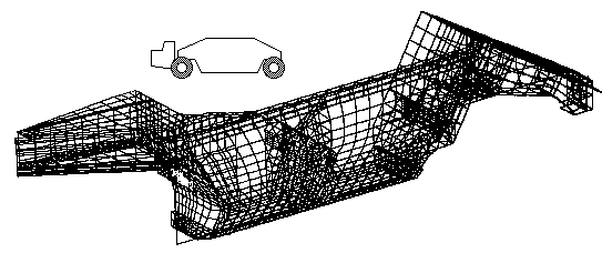
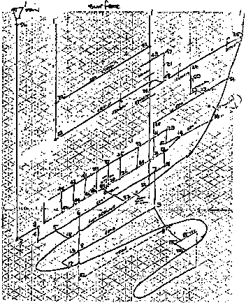
Each airway is essentially a flow resistance element, the resistance being a function of length, cross-sectional size, wall roughness etc. The airway junctions ( nodes ) are numbered sequentially in the sketch. The system is thus a 1-net, ie. a network of line elements, each line connected between two nodes.
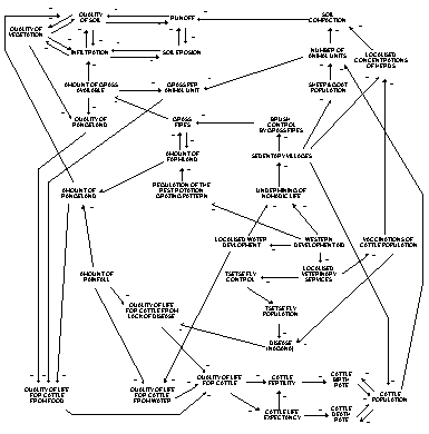
The sketch only goes so far as to identify the causes and effects between related factors in this study in the field of Agricultural Economics.
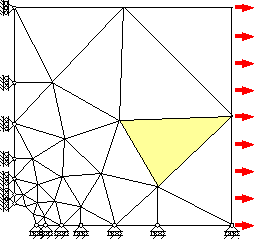
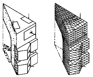
Only one quarter of the symmetric prototype is modeled thus conserving memory without sacrificing accuracy ( or increasing the accuracy possible with limited memory ).
The model supports are chosen to minimise constraints thus mimicing the prototype and preventing rigid body motion.
The idealised model of the slice appears on the left; the corresponding finite element assembly on the right. Supports are not shown.
The sketch shows the mesh both before and after deformation.
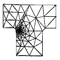
The elements are two-dimensional, either triangular or quadrilateral - and unlike the elements of FEM1 above, support both in- and out-of- plane loading.
