FRACTURE MECHANICS
Fracture Mechanics is the study of cracks and crack-like defects - such as might occur in welds for example - with a view to understanding and predicting the cracks' growth tendencies. Such growth may be either stable - that is relatively slow and safe - or unstable, virtually instantaneous and catastrophic.
Let us first reiterate some familiar topics from Strength of Materials to set the scene for Fracture Mechanics concepts . . . .
| Ductiles vs Brittles - their relative behaviour under the conventional, slow tensile test.
|
| | ductile | brittle
|
|
| 
| 
|
| | Slow controlled extension; final instability due to gross area reduction. Cup -and -cone failure surface characterised by 45o shear lip. | Fast catastrophic failure with no warning. Transverse granular cleavage surface - no shear lip.
|
|
| 
| 
|
| | Relatively high energy absorption capacity ( stress -strain area ) - "tough". | Low energy absorption capacity.
|
| | Localised yielding at high stress concentrations redistributes stresses advantageously. | No significant yielding so no reduction of high stresses.
|
| | Shear causes failure, triaxiality is relatively benign. | Triaxial stresses cause failure, unlike ductiles.
|
Fatigue of Ductiles
|
|
|  Fatigue is recognised as a mechanism of crack growth terminated by catastrophic fracture - hence the S-N diagram which may be used to predict failure. If we can understand, and formalise mathematically, the fundamentals of the crack growth process and the interaction between the factors which affect it, then the onset of catastrophe may be predicted more confidently - rather than having to rely upon a somewhat contrived correlation between S-N curves, notch sensitivity, stress concentration and the like.
But this is not the only advantage ! There are many well documented catastrophies which cannot be explained by conventional steady state safety appraisal or fatigue arguments :
- Ocean-going vessels have been known to break in two since time immemorial - but not while they were berthed ! Some catastrophic maritime fractures are illustrated briefly.
- The de Havilland 'Comet'
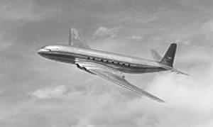 was the first jet-propelled airliner. It entered commercial service with BOAC in 1952 and was successful until a series of unexplained mid-air disintegrations forced its grounding in 1954 well before approaching the end of its expected fatigue life. Subsequent examination of wreckage from the bottom of the Mediterranean and fatigue pressurisation of a full size fuselage confirmed that explosive decompression was due to catastrophic advance of fatigue cracks in escape hatch surrounds ( Neil James provides further interesting details ).
The state-of-the-art technical leader turned out to be a commercial disaster.
|
| | Fracture Mechanics currently offers the only satisfactory route to understanding these and similar problems.
|
Stress Concentration
|
|
|  The effect of plasticity in way of high stress concentrations in a ductile tensile member is reviewed here. The long bar a-b-c-d-e, subjected to a uniform tensile load over its ends, can be expected to fail first at e as the load is increased. Why? Because it is here that the geometric singularities are the most severe, and hence stress concentrations are highest.
Regarding nomenclature, if the load at some stage is 1 kN, then, in c, d, e :-
σa = 1000/5 = 200 MPa is referred to as the 'background' stress
σb = 1000/4 = 250 MPa is referred to as the average 'ligament' stress
Consider the notional stress distribution across the ligament of e under this load if the material is elastic- perfectly plastic with a yield strength of 400 MPa. The simplistic model
 of uniform stress is untenable due to the stress concentration at the root of the crack.
If the material had been linear elastic then this stress concentration could lead to a peak stress of say 500 MPa.
However the material cannot support stresses greater than yield, so the actual distribution will be more as sketched on the right. The fact that some material has reached yield is not particularly deleterious as it offers load support and is backed up by adjacent sub-yield elastic material.
If this material had been brittle with an ultimate strength of 400 MPa, then the peak stresses would have corresponded to the linear elastic case and the bar would have broken at a load of 800 N.
'Notch sensitivity' is a measure of a ductile material's inability to shrug off localised stress concentrations.
|
Temperature / Rate Effects
|
|
| These effects have a marked influence on a material's ability to withstand loads. Cracks and low temperatures are most unhappy bedfellows - as evidenced by many weld failures at low temperatures. The pressure vessel Code for example, makes special provision for welded vessels at low temperatures.
In both the slow tensile test and in the fatigue of a ductile material, the final stage of failure is brittle ( ie. unstable ) since the crack speed is so high that the material's toughness has been reduced to a value which is more characteristic of a brittle material.
This is partly the reason for the 'unzipping' of sub-sea pressurised pipelines, with disastrous consequences. Although these ductile pipes are designed via cylinder theory with the usual factors of safety against yield, the pipe material behaves in a brittle fashion at the propagation speeds involved. Furthermore, since
- a crack advances at the speed of sound in the metal wall ( around 2 km/s ), and
- a pressure pulse travels only at the speed of sound in the fluid ie. less than the above
. . . then it follows that the crack front is subjected always to the original pressure of the fluid and a leak is NOT self- relieving.
|
The Column Analogy
|
| The behaviour of a crack of characteristic length a loaded by a background stress σ is similar to that of a column of length L loaded by the force F.
|
|
|
| column
|  If ideal loading is wholly elastic then the load may be increased, slowly and with complete safety, until it reaches the critical Euler load, Fc, governed by elastic instability, whereupon catastrophe is immediate. If ideal loading is wholly plastic on the other hand then the material's yield strength limits the load that can be applied. Failure in practice is governed by elastic- plastic interaction - such as the dashed blue locus of the sketch.
| | crack
|  If ideal loading is wholly elastic then the load may be increased, slowly and with complete safety, until it reaches the critical LEFM load, σc, governed by elastic instability, whereupon catastrophe is immediate. If ideal loading is wholly plastic on the other hand then the material's yield strength limits the load that can be applied. Failure in practice is governed by elastic- plastic interaction - such as the dashed blue locus of the sketch.
Additionally in the case of a crack the failure locus may be reached by various paths - for example the load may remain constant while the crack length increases in a controlled manner, until eventually a critical length is reached and the crack front advances catastrophically.
|
|
With this background in mind, we can summarise what Fracture Mechanics is and does. It . . .
. . . presupposes the existence of cracks in the material, which may be
- microscopic ( grain cleavage or surface roughness for example ), or
- large ( casting or weld defects for example )
- due to manufacture, to corrosion, to fatigue, &c
. . . correlates three parameters quantitatively . . .
- load - the background stress, σ, for example
- geometry - the crack size, a ( and to a lesser extent, crack shape )
- material - its resistance to cracking ie. its fracture toughness Kc measured by special tests
. . . and predicts, amongst other things
- degree of safety, or imminence of catastrophic ( brittle ) fracture
- crack growth rate whilst advancing in a controlled manner
- component life which remains.
The application of Fracture Mechanics can thus be regarded assomewhat similar to the conventional use of design equations, viz :-
function ( material, load, geometry, "degree of safety" ) = 0
however it should be understood that, at its present level of development, Fracture Mechanics is less precise than conventional stress-strength-safety analyses. The predictions mentioned above cannot therefore be viewed with quite the same confidence afforded conventional safety factors.
As noted previously, temperature and rate effects are both significant parameters in the crack propagation process. They affect the material's fracture toughness generally
 in the manner sketched.
The effect of a change of loading /crack growth rate is to move bodily the fracture toughness curve parallel to the temperature axis. This, together with the shape of the curve, means that a higher rate or lower temperature will decrease fracture toughness.
Also indicated on the sketch are the regions in which the various failure mechanisms dominate. When the material's resistance to crack growth is low, elastic crack instability is the dominating failure mechanism; plastic effects are negligible and the material behaves in a brittle, linear elastic manner analogous to a long Euler column. Fracture mechanics in the absence of plastic effects is known as Linear Elastic Fracture Mechanics ( LEFM ).
Conversely, if fracture toughness is high then failure is dominated by plastic yield - elastic instability is relatively insignificant as in the analogous case of a short column.
As with column buckling, we shall start by examining linear elastic instability ( LEFM ) before introducing the effects of plasticity and demonstrating simple techniques for handling mixed mode ( elastic- plastic ) fracture.
 Copyright 2005 Douglas Wright, doug@mech.uwa.edu.au
last updated May 2005