Bending strength
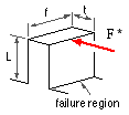 As a first approximation the tooth is modelled as a cantilever of rectangular cross-section and length L and subjected to the damaging load, F*. The maximum bending stress at the critical failure region is :-
σ = M y / I = ( F* L ) ( t /2 ) / ( f t3 /12 ) and
∝ F* /m f since, for geometrically similar teeth, both t and L are proportional to the 'size', ie. to the module, m. So :
( 17 ) σ = F* / m f J
in which the AGMA proportionality constant, J, is known as the bending strength geometry factorand
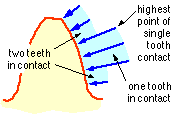 is evaluated by photo -elastic or finite element methods. It correlates the stress in the simple cantilever model with the actual maximum stress in a gear tooth, which is influenced by stress concentration, by variation in load direction and moment arm length, and by load sharing between teeth as the contact point moves along the tooth as suggested by the sketch - though the two statically indeterminate teeth pairs prevent the sudden steps sketched.
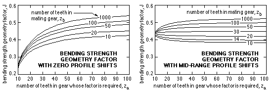
The factor's value depends upon the number of teeth and profile shift of both gears and is obtainable from AGMA 2001 or calculated by the Macintosh program "Steel Spur Gears"is based on AS 2938. Its variation is graphed below when both profile shifts are zero and when they are both at the middle of the practical range ( Fig G).
The graphs demonstrate that without profile shifts, J-factors decrease and stresses ( 17) increase markedly with decreasing tooth numbers - however with small numbers of teeth, significant increases of J-factor and reductions of stress result from incorporating suitable profile shifts. When both profile shifts are mid-range the J-factor may be approximated by :
( 18 ) J ≈ { 0.535 + ( - 3.030 + 14.5 / zb ) /zb } + { - 0.904 + ( 28.43 - 147.0 / zb ) /zb } / za
in which za is the number of teeth in the gear whose J-factor is required and zb is the number of teeth in the mating gear.
Combining ( 12) ( 15) ( 16) and ( 17) leads to the final design equation for tooth bending strength which is applicable to each of two mating gears :
( 19 ) ( π m3 β N1 z1 / Ka Kv Km KR P ) . ( J Sb KL ) i ≥ 1 ; i = 1,2
where Sb is the allowable bending stressfor the gear tooth material.
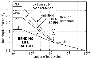
The first bracketed term of ( 19) is common to both gears, noting that N1 z1 = N2 z2. In the analysis situation, the two bending life factors KL and hence the lives of the two gears may be evaluated individually from the equations ( 19). In design, a trial module or face width is often selected which must satisfy the inequalities ( 19) for both gears, whose minimum life would be specified - the weaker gear, that with the lesser J.Sb .KL product, dictates the minimum module acceptable.
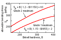
| As an indication of the information available in AGMA 2001, the maximum allowable bending stresses for two grades of through -hardened carbon steel gears are shown here as functions of Brinell hardness - the differences between the grades are metallurgical as explained in AGMA 2001, which gives also allowable stresses for other materials. These stresses are the result of extensive gear testing; attempts to deduce them from other material properties such as the reversed bending endurance limit are ill advised.
|
| AGMA proposals for the bending life factor, KL, of steel gears (except nitrided) are as shown - however values are influenced by factors other than the Brinell Hardness.
We shall consider application of this theory once the theory for the other failure mechanism, pitting, has been developed.
| 
|
 Copyright 1999-2005 Douglas Wright,
doug@mech.uwa.edu.au
last updated December 2005
 is evaluated by photo -elastic or finite element methods. It correlates the stress in the simple cantilever model with the actual maximum stress in a gear tooth, which is influenced by stress concentration, by variation in load direction and moment arm length, and by load sharing between teeth as the contact point moves along the tooth as suggested by the sketch - though the two statically indeterminate teeth pairs prevent the sudden steps sketched.
 As a first approximation the tooth is modelled as a cantilever of rectangular cross-section and length L and subjected to the damaging load, F*. The maximum bending stress at the critical failure region is :-
