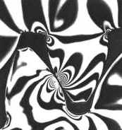
Photoelasticity is used to estimate the stresses in a loaded element. Polarised light is transmitted through the transparent model of a slice of the element. The model deforms under load, causing the transmitted beam to interfere with a reference beam.
The resulting interference pattern consists of a series of bands, each representing an area of constant prototype stress whose value can be predicted by calibration and by counting bands from unloaded areas. Qualitatively, the closer these bands are bunched up in the model, the higher are the prototypical stresses.
The photoelastic results of contacting gear teeth shown here have important implications for tooth safety :
The following treatment of gear reliability is a gross simplification of the American Gear Manufacturers Association (AGMA) code of practice, AGMA 2001. The treatment aims to demonstrate one approach to fatigue design rather than to transform the reader into a gearing expert.
Apart from one-off overloads, there are three common modes of tooth failure
Since fatigue is prevalent in the other two failure modes, the AGMA employs a reliability approach rather than a safety factor approach in assessing a tooth's tolerance of damage - its bending strength and its pitting resistance. In a reliability analysis, knowledge of a component's load-life (S-N) relationship enables a load to be considered from the point of view of its effect on component life rather than whether it leads to total failure or to total non-failure. A smaller load increases life, a larger load reduces life; whether the safety factor is greater or less than one is irrelevant - indeed the whole concept of safety factor is inappropriate in the context of reliability.
In the succeeding sections therefore, we first determine the effective damaging tooth force F* due to the power transmitted and the shock / vibration intrinsic to the gears' manufacture and operational environment. The stress, σ, due to this force is then deduced from bending theory, or from Hertzian contact theory in the case of pitting, and the resulting life follows from the load-life curve appropriate to bending or to contact fatigue as the case may be.
It will be recalled that the load-life diagram for a particular material and given type of loading is generally of the form illustrated, with curves corresponding to different survival rates being approximately parallel to one another - the 99% survival curve eg. implies that one sample in a hundred fails to reach the life given by the curve for a particular load. We shall consider only steel materials (carbon steels induction- or through-hardened, nitrided alloy steels etc). Rather than provide the complete load-life diagram for each steel, the AGMA chooses a reference point on the curve corresponding to 99% survival rate after 107 unidirectional loading cycles, and cites the corresponding allowable stress, S, as a representative property of the steel. So, for any given load ( σ) the life and survival rate (reliability) may be correlated through :
( 12 ) σ = S ∗ life factor ( KL or CL ) / reliability factor ( KR ) where :
| RELIABILITY FACTOR | % survival | KR |
| fewer than one failure in 10,000 | 99.99 | 1.50 |
| fewer than one failure in 1,000 | 99.9 | 1.25 |
| fewer than one failure in 100 | 99 | 1.00 |
| fewer than one failure in 10 | 90 | 0.85 |
Further explanation of the derivation of ( 12) is presented here.
These aspects when combined will result in gear tooth design equations, one for bending strength and one for pitting resistance, which embrace load (transmitted power), dimensions (primarily size characterised by module), material (allowable stress) and life rather than safety.
It will be recalled that the free body of a gear pair necessitates identical senses of the torques on pinion and wheel - Fig L below repeats the essentials of Fig J with clockwise torques. Two teeth are in contact at the point C on the line of action, which is tangential to the two base circles and inclined at the pressure angle, α. ( Strictly, parameters corresponding to extended centres should be considered here, but this sophistication is not necessary for the present introduction to gear reliability. )
( 13 ) T i = F Roi = F ( R i cos α ) = ( F cos α ) R i = Ft R i ; i = 1,2
where Ft is the useful tangential component of the contact force at the pitch point. The radial component, Fr, is useless and tends only to separate the gears (or pitch cylinders) - note that ( 13) tallies with ( 1) which neglected Fr.
The pressure angle in Fig L should more correctly be the extended value, and correspondingly ( 13) should really be cast in terms of the actual pitch radius. We neglect such niceties in the present general development.
The steady power transferred, P, is :-
( 14 ) P = ω i T i ; i = 1, 2 the power transfer in rotational terms equals
= ω i Ft R i = Ft v the power transfer in translational terms, from ( 1)
Athough the positive drive ensures that there is no speed loss, there will be torque and power losses due to sliding. Spur gear efficiencies exceeding 99% have been reported, however a value of around 96% is more appropriate for run-of-the-mill design - this allows for bearing and aerodynamic losses in addition to tooth friction.
Gear analysis or design usually starts with a known time-averaged (ie. steady) power transfer - these last equations enable the uniform transmitted load Ft to be found. The corresponding failure-producing (ie. damaging) load F* will be greater than Ft because of shock, vibration caused by less-than-perfect tooth profiles and mounting rigidity, and so on. We write :
( 15 ) F* = Ka Kv Km Ft
in which the various empirical K-factors, all ≥ 1, each reflects the extra damage caused by a particular, separately identifiable practical non-uniformity, as follows :-
| Ka | is an application factor to allow for the non-uniformity of input and/or output torque inherent in the machinery connected to the gears. Typical values are :-
| |||||||||||||||||||||||||
| Kv | is a dynamic factor which accounts for internally generated tooth loads induced by non-conjugate action of the teeth, by gear mesh stiffness variation, by gear imbalance and the like.
The AGMA code defines a transmission accuracy level number, Q, which reflects these latter (high Q implies low excitation, a low Q refers to low accuracy and high vibration) and suggests the Kv factors shown below, expressing them empirically as follows (with velocity v in m/s) :-
Kv does not account for vibration induced by running near shaft critical speeds or by other resonances - these should be avoided or separately catered for. Note that the AGMA defines Kv as the reciprocal of the Kv used here. | |||||||||||||||||||||||||
| Km | is a load distribution factor which reflects the non-uniformity of tooth loading over the face width of the teeth, arising from gear and mounting inaccuracy, elastic deformation of shafting and the like.
For a face width f (mm) the AGMA proposes the empiricisms :
| |||||||||||||||||||||||||
( 16 ) f = β m where, usually, 9 ≤ β ≤ 15 for economic gears -
These limits should not be regarded as inviolable, but costs should be expected to escalate if they are exceeded.
We have seen how to evaluate ( 15) the damaging fatigue load on a gear tooth, F*, due to the torque transmitted combined with the quality of the gear's manufacture and its operating environment.
| - | a rectangular cantilever in bending, or |
| - | a pair of cylinders in Hertzian contact |