Compensation, or reinforcement,is the provision of extra stress-transmitting area in the wall of a cylinder or shell when some area is removed by boring a hole for branch attachment. The principle is sketched.
|
|
Provided that the longitudinal welds in both shell and branch do not lie in the critical longitudinal planethen - from a compensation point of view - both t and tb would be reckoned from ( 1) with η = 1. The thickness differences ( T - t ) and ( Tb - tb ) contribute to compensation - though reinforcement is ineffective beyond the limits Ln normal to the vessel wall, and Lp from the branch centreline parallel to the wall, as shown below for a set-in branch :-
 |
Usually the first of the Lp limits, Db, controls. However a compensating area cannot contribute to more than one branch, so if the spacing of two branches Db1 and Db2 is less than ( Db1+ Db2 ), then by proportion Lp1 = Db1 . spacing/( Db1+ Db2 ).
Furthermore, if the branch is attached to a dished end, then no compensation area is effective if it lies outside the aforementioned 80% limits. If the head is torispherical, the hole should lie in the spherical portion and t will be given by ( v). If the head is ellipsoidal, then AS 1210 defines an equivalent sphere for the application of ( v), since the hole will not lie close to the rim region of sharp curvature which dictates the thickness via the stress concentration factor in ( vii).
Within the Ln, Lp limits, compensation requires that :-
( xi) A1 + A2 + A3 + A4 + A5 ≥ A = Dbt
The inward protrusion '3' is subjected to corrosion on three surfaces but there is no pressure differential across it; it will not exist for a set-on branch. The sketch indicates that:-
( xii) A1 = ( 2Lp - Db - 2tb ) ( T - t ) ; A2 = 2Ln ( Tb - tb ) etc.
These equations should be compared carefully with the corresponding equations in AS 1210 to clarify the restrictions implicit in the Code.
Compensation should be disposed symmetrically about the hole and as close to the hole as possible. It is usually more economical to increase the branch thickness than to provide a separate reinforcing ring, however such an increase should not be excessive.
It will be appreciated that the principle of compensation is very simple and ignores inevitable stress concentrations - hence the substantial safety factors mentioned above. AS 1210 lays down branch size upper limits beyond which this simplistic approach is no longer permissible, namely :-
Maximum branch bore = minimum ( Di/2, 500 mm ) if Di ≤ 1500 mm, or
= minimum ( Di/3, 1000 mm) if Di > 1500 mm
Strictly, reinforcement ought to be checked in all planes which contain the branch centreline; AS 1210 defines A = FDbt where F is a factor which varies between unity for the longitudinal plane considered above, and 1/2 ( ie. σa/σt ) for the transverse plane. Generally such a check is unnecessary.
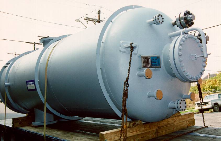
A single opening, 75 mm diameter or less in plate 6 mm thick or greater, does not require compensation. Short pipes of this size are sometimes welded straight into the shell as in the photograph, however not only is the pipe prone to damage, but if the pipe thickness differs appreciably from the shell thickness then welding could be awkward.
Each pipe is equipped with a flange welded to the outboard end - once the vessel has been installed permanently, the mating pipe can be attached by bolting the flanges together with a gasket between them to prevent leakage (refer eg. to the chapter on Threaded Fasteners).Alternatively, and perhaps more cheaply, a flange may be welded directly into the shell to obviate the need for a short pipe.
It's time we now looked at flanges and other details including manholes and vessel supports.