Thin Shells of Revolution - Heads
The stresses in a pressurised thin axisymmetric shell of revolution will now be considered so that the behaviour of dished ends may be appreciated.
The shell is formed conceptually by rotating the meridian, a curved line of selected shape lying in the r-z meridional plane, about the z-axis.
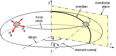 The resulting surface of revolution is clothed by a small, symmetrically disposed thickness t, and the resulting shell loaded by internal pressure p. If the meridian were a straight line for example, parallel to the z-axis and distant D/2 from it, then the shell would be a cylinder of diameter D.
These shells are similar to thin cylinders in that radial stresses are negligible and the membrane stresses :
- the circumferential or hoop stress σθ (that is σt of cylinder theory) and
- the meridional stress σφ (analogous to σa of cylinder theory)
can both be found from equilibrium since they, and the loading, are axisymmetric.
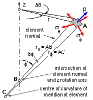
Consider the element located at the point A in the r-z plane as shown, and defined by φ, δφ and δθ. The local surface normal cuts the z-axis at the point B, AB being defined as the radius rθ. The centre of curvature lies at C on the normal, AC being the instantaneous radius of curvature of the meridian, rφ.
The components of the pressure and stress resultants along the outward normal are :
- pressure : p δA = p ( r δθ ) rφ.δφ
- meridional stress : - 2 σφ ( t r δθ ) sin δφ/2
- circumferential stress : - 2 σθ ( t rφ δφ ) sin δθ/2 . sin φ
Taking limits and noting that r = rθ sin φ, then equilibrium of the element requires that :-
( ii) σ&theta / r&theta + σφ / rφ = p / t the so-called membrane equation

Furthermore, for vertical equilibrium of the dish area above the hoop :-
( iii) π r2 p = 2 π r t σφ sin φ
Solving equations ( ii) and ( iii) gives the stress components in terms of rθ and rφ , which are in turn functions solely of the meridional geometry - its shape and location with respect to the rotation axis :
( 2) σφ = ( p /2t ) rθ ;
σθ = σφ ( 2 - rθ /rφ )
Some typical specialisations of ( 2) are as follows :-
- Cylinder
- rθ = D/2 and rφ tends to infinity - therefore from ( 2)
( iv) σθ = 2σφ = pD/2t ie. the thin cylinder equations once again.
- Sphere
- rθ = rφ = D/2 and so from ( 2)
( v) σθ = σφ = pD/4t
- The sphere is an ideal end closure since the stresses are less than those in other shapes, however the degree of forming necessary renders it impractical except for very high pressures when the manufacturing cost may be justified.
- Ellipsoid
- An elliptical meridian of semi -major and -minor axes a, b and eccentricity ε = √[ 1 - (b/a)2 ], is rotated about the minor axis to form the head of the cylinder whose diameter is D = 2a as sketched below.
The location of an element on the ellipse is defined most directly by the radius r from the rotation axis, however it will be found more convenient to define the alternative independent variable u = √[ 1 - ε2 ( r/a )2 ] where u = f (r) and b/a ≤ u ≤ 1.
The geometry of the ellipse may be invoked to derive the radii of interest ( 2) in terms of u (ie. in terms of r) :-
rφ = (a2/b) u3 ; rθ = (a2/b) u
The stresses at the r-element follow immediately from ( 2) as :-
( vi) σφ = ( pa2/2bt) u ; σθ = σφ ( 2 - 1/u2 ) where u = f ( r ) as defined above
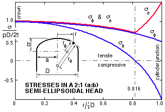
- These stresses are graphed for a = 2b, the most common proportions for practical ellipsoidal ends. The prominent feature of this stress pattern is the tensile- to- compressive transition of the hoop stress at about 80%D.
|
-
Consequences of compressive behaviour include :
- a propensity for local buckling.
- an increase in the equivalent stress - assuming the maximum shear stress theory for example with the third principal stress (the radial) zero,
- a significant incompatibility between cylinder and head, due to different senses of the hoop (ie. diametral) strain - under pressure the cylinder tends to expand, and the ellipsoidal end to contract diametrically at the junction. Bending moments in the walls of the cylinder and head are therefore set up at the junction, with corresponding bending stresses. These relatively minor secondary stresses cannot be explained by membrane theory, but other work shows that they become insignificant at a distance of about five times the wall thickness from the junction.
Tensile strains in the cylinder at the junction tend to relieve the compression in the dished end and for this reason the stress concentration factors K cited in AS 1210 are less than might be inferred from the above graph - for example :-
( vii) S ≥ K pD/2tη where K = [ 2 + (a/b)2 ] / 6
ie. for a/b = 2, K = 1 and not the 1.5 graphed above.
- Torisphere
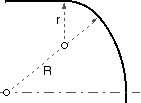
- Another common shape for a dished end is torispherical. This consists of a spherical central portion of radius R and a toroidal knuckle of radius r, where R/r is often 12 or thereabouts, and R is about 95 % of the cylinder diameter. Junctions of the torus with both sphere and cylinder give rise to geometric singularities and hence to secondary bending stresses as discussed above. The AS 1210 stress concentration factor, M, reflects this behaviour :-
( viii) S ≥ M pR/2tη ; M = [ 3 + ( R/r )1/2 ] / 4
- - the greater the deviation from a sphere ( R/r = 1), the larger the factor. Noticeably, the highly stressed region again extends outwards from about 80% D. Torispherical ends are often preferred to ellipsoidal since the depth of drawing is less and hence they are slightly cheaper - about 10% on average - but this is often outweighed by their higher stress concentration and consequent lesser allowable pressure for a given size.
Dimensions are taken to the wall mid-surface in ( vii), ( viii).
The great majority of heads are seamless, being manufactured from discs either pressed, or spun in the larger sizes. Theoretically for a seamless head η = 1 in ( vii), ( viii) - however to allow for thinning which results from drawing, the pressure ratings in one commercial brochure are based on η = 0.875 for thicknesses ≥ 25 mm and 0.85 for thicknesses < 25 mm.
Heads are always provided with a short ' flat ' ie. the heads are manufactured with a short integral cylinder, to avoid the junction weld coinciding with stress concentration due to the head- to- cylinder incompatibility and the small head radii of curvature.
Flat plate end closures are not suitable in larger sizes, though often used for doors - being flat, there are no membrane stresses and pressure is resisted solely by plate bending. We have noted already that, for a given load, bending stresses are generally much larger than direct (eg. membrane) stresses. Flat plates therefore have to be much thicker than dished ends for similar duty.
Having formed the pressure vessel shell from a cylinder with two heads welded thereto, holes must be bored and short pipes (or branches) attached through which fluids enter and leave the vessel. A manhole also may be necessary to allow workers' access to the interior for manufacture or inspection. Holes obviously remove stress- transmitting material, and this removal must be made good somehow. This brings us to the concept of compensation . . . .
 Copyright 1999-2005 Douglas Wright,
doug@mech.uwa.edu.au
last updated May 2005
 The resulting surface of revolution is clothed by a small, symmetrically disposed thickness t, and the resulting shell loaded by internal pressure p. If the meridian were a straight line for example, parallel to the z-axis and distant D/2 from it, then the shell would be a cylinder of diameter D.


