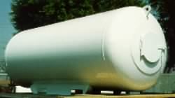
Air receivers and LNG tanks are two common examples of pressure vessels. They are usually cylindrical in form and hence employ cylinder theory in their design, but there are numerous practical aspects which transcend the basic theory - end closures have to be fixed to the cylinder, holes have to be cut and inlet/outlet pipes ( branches or nozzles ) attached, weld flaw probabilities have to be acknowledged, and so on. Some of these aspects are now examined, as a lead- up to the practical design of pressure vessels.
|
|
( i) S = minimum ( Sy /1.6 , Su /4 , SyT /1.5 , Scr /1.6 )
in which Sy and Su are the tensile yield and ultimate at room temperature, and the last two terms are applicable only at design temperatures above 50oC, SyT being the yield strength and Scr the 100 000 hr creep rupture strength at the design temperature.
Minimum mechanical properties are laid down in AS 1548 Steel Plates for Boilers and Unfired Pressure Vessels, a steel being referenced typically as 'AS1548-2-430-H' in which the '2' refers to Section 2 of AS1548 which deals with a particular type of steel, '430' denotes the minimum ultimate (MPa), and 'H', if it appears, indicates that properties have been verified by high temperature testing rather than being inferred from room temperature properties. Note that properties are slightly thickness- dependent.
In design, corrosion which occurs over the life of a vessel is catered for by a corrosion allowance, c, whose design value depends upon the vessel duty and contents' corrosiveness - for example 1 mm is typical for air receivers in which condensation of air moisture is normally inevitable. It is important to realise that when dimensions in any formula refer to a corrodable surface, then the dimensions inserted into the formula are those at the end of the vessel's life, when all the corrosion allowance has been eaten away. So, if a plate is of nominal thickness T now, and is subject to corrosion on one side, then ( T - c ) must be substituted whenever nominal thickness appears in an equation. Similarly a tube of current bore Di which corrodes will have a bore of ( Di + 2c ) at the end of its life.
Welded joints are not as strong as the parent plate unless welds are thoroughly inspected and, if flawed, repaired during manufacture - all of which is expensive. This strength reduction is characterised by the weld or joint efficiency η = joint strength / parent strength - which varies from 100% for a perfect weld (ie. virtually seamless) through 75-85% for a tolerably good weld.
Consider the three bars illustrated below which are all of the same width b and material strength S and which are loaded by the tensile load P. The first bar is seamless of thickness ts and the second welded with joint efficiency η and thickness tw locally at the joint. The safety factor in this second bar is Sbts / P away from the joint and ( η S) btw /P at the joint. If in design these safety factors are to be identical (ie. the bar is not to be weakened by the joint) then tw must equal ts /η.
|
Pressure vessel cylinders
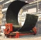 are usually made from flat plates which are rolled then welded along longitudinal joints.
On the other hand, circumferential joints are used to attach end closures ( dished ends or heads ) to the cylinder, and to weld together rolled plates for a long vessel if plate size availability or rolling machine capacity are restricted.
Weld types and efficiencies usually differ for longitudinal and circumferential joints, and therefore the joint stresses in a vessel must satisfy both the requirements :-
| longitudinal joint, | efficiency η l , | circumferential stress | σ c = p D / 2t ≤ η l S | |
| circumferential joint, | efficiency η c , | longitudinal stress | σ l = p D / 4t ≤ η c S |
( 1) t = maximum ( pD/2η lS , pD/4η cS )
In this formula, AS 1210 takes the diameter to be the mean at the wall mid-surface ( D = Di + t ) though it quotes the equation conveniently in terms of Di . As the circumferential stress is twice the longitudinal it follows that the first of these inequalities is usually controlling - provided that η c is greater than half η l, which is commonly the case. A plate thickness T, such that ( T - c) ≥ t, would be chosen from a commercially available range such as the BHP plate size schedule, referred to in Problem 3 below.
The Code defines four classes of vessel manufacture - 1, 2 ( A & B )
 and 3 - and provides details of the weld types and efficiencies which are permissible in each class. Some of the major differences between the classes are summarised in the table below; other requirements such as certification of welders' skills need not be gone into here. The sketch indicates that the most expensive Class 1 vessels are mandatory if failure is potentially lethal, no matter what the thickness. Class 2 vessels having a wall thickness greater than 32 mm are inadmissible, and so on. All steel vessels are hydrostatically tested after manufacture to 150% of the design pressure.
| Class of vessel | 1 | 2A | 2B | 3 |
| Plate thickness, T mm | no limit | T ≤ 32 | T ≤ 12 | |
| η l (double butt mandatory) | 1.0 | 0.85 | 0.75 | 0.65 |
| η c | - - - depends on weld type, usually less than η l - - - | |||
| Heat treatment | required | - - - not required - - - | ||
| Radiographic examination | required | spot | - - - not required - - - | |
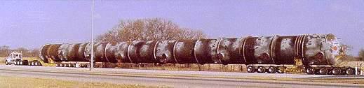
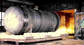 A pressure vessel is shown entering a heat treatment furnace - clearly the cost associated with heat treatment is not negligible.
It is apparent that in the design process, the selection of class (if scope for choice exists), and of weld type, involves an economical balance between welding costs ( including inspection and repairing flaws during manufacture, if carried out ) and the cost of plate - a categorical decision cannot be made until the relative or total cost of all potential candidates can be compared.
Welds should preferably not be situated adjacent to anomalies such as stress concentrations or inhomogeneities due to other welds, especially major structural welds. Hence the staggering of the two longitudinal welds in the sketch above.
The two ends of the cylindrical portion of a pressure vessel are usually closed off by dished ends (or heads as they're often called) welded to the cylinder. Heads are available in various shapes and sizes, and we must be able to design them in the same way as we can design the cylindrical components . . . . so let's now look at thin shells of revolution . . . .