EXAMPLE
A return spring of infinite life (ie. 107 cycles) is required for a cam follower which moves through 25 mm, 400 times a minute. The spring must fit over a Φ 15 mm shaft and inside a Φ 65 mm hole, and it must exert a force which varies between 300 and 600 N. Design a suitable spring with closed and ground ends, made from ASTM A229.
Although the material specified is not optimum for fatigue applications, the solution to the problem will be a useful benchmark for other solutions. A small safety factor of 1.1 will be selected for reasons given previously and presuming the consequences of failure are not severe.

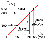
Completing the characteristic, given δhi - δlo = 25 mm, Flo = 300 N and Fhi = 600 N, it follows that the spring stiffness must be k = ( 600 -300)/25 = 12 N/mm, and further δlo = 25 mm, δhi = 50 mm.
Assuming a 12% clash allowance, then δs - δhi ≥ 0.12 δhi, so take δs = 56 mm and hence the solid load is Fs = kδs = 672 N.
This completes the characteristic as sketched.
The mean and alternating load components are Fm = 450 N and Fa = 150N, so, from ( 5b) with Sus/Sut = 0.63 and Ses/Sut = 0.13 for A229 from Table 2, and taking forces in N :
( a) Fe = ( 2 x 450/0.63) C Ks + ( 2 x 150/0.13) C Kh
= C ( 1430 Ks + 2310 Kh ) - a function of C only, from ( 1).
In order to obtain a ball-park estimate of the wire diameter necessary, assume C = 7.5 which lies midway in the usual recommended range. From ( a) it follows that Fe = 7.5 ( 1430 x 1.07 + 2310 x 1.19) = 32.1 kN, so that the tensile capacity of a wire suitable for this fatigue application is Fut = nFe = 1.1 x 32.1 = 35.3kN.
From Table 3, a suitable wire diameter lies somewhere between 5 and 6.3 mm; so a table of candidate solutions is prepared for solutions based on wire diameters in this range from the R20 series of AS 2338. Succeeding rows of the table assess the practicability of each candidate wire diameter by addressing :
| wire diameter | 5.6 | mm | |
| mean coil diameter | 38.7 | mm | |
| total number of turns | 16.0 | ||
| free length | 146 | mm | |
| ends squared and ground. |