The fundamental operation in manufacture is the creation of shape - this includes assembly, where a number of components are fastened or joined together either permanently by welding for example or detachably by screws, nuts and bolts and so on. Since there is such a variety of shapes in engineering to be assembled, it is hardly surprising that there is more variety in demountable fasteners than in any other machine element. Fasteners based upon screw threads are the most common, so it is important that their performance is understood, and the limitations of the fastened assemblies appreciated.
There are two distinct uses for screw threads and they usually demand different behaviour from the threads :
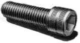
A screw ( iii) is similar to a bolt - the names are often loosely interchanged - though strictly a bolt is equipped with a nut which is rotated to tighten the assembly, whereas a screw is itself rotated and engages with a threaded ( or 'tapped' ) hole in a stationary component such as an engine block casting. The screw illustrated has no shank, being threaded right up to the head.
There is a great variety of screw head forms available.
The ubiquitous socket headed setscrew shown here is tightened by a hexagon wrench rather than by a spanner.
A stud ( iv) has no head and is threaded at both ends. The ends are
 not necessarily the same. One end is screwed into one of the components usually before the second component is assembled. The sketch illustrates also :
| 
|
 Salient geometric features of the thread are illustrated in ( v). The distance between similar points on adjacent threads is the thread's pitch.
( 1) σ = Fb / As where As is the stress area - a function of thread size and geometry.
Since the stress area is less than the cross- sectional area of a normal (non-reduced) shank, the exposed threads are usually the most critically loaded part of the assembly - this is why failure of threaded joints occurs most commonly close to the nut face.
A thread can be likened to a piece of string wound in a tight helix around a cylinder - or around a conical frustum in the case of pipe thread designed to eliminate leakage.
When a nut on a screw is rotated by one turn, it travels along the screw a distance known as the lead L. Developing one turn of the thread at the mean diameter dm ( the average of major and minor diameters ) gives the lead angle ( or helix angle ) λ as tanλ = L /π dm .
Power screws may employ multiple threads, or starts, so L = p ∗ number of starts as illustrated. Fasteners on the other hand are almost invariably single start ( L = p ). They are also right handed to avoid confusion in tightening, though LH screws appear in turnbuckles and in certain bicycle parts where the prevailing torque would tend to loosen RH fasteners.
A thread 'system' is a set of basic thread proportions which is scaled to different screw sizes to define the thread geometry. Whitworth, Sellers,
 British Standard Pipe (BSP) are just three of the many systems which proliferated before the adoption of the ISO Metric thread system. Since this last is now universal, it alone is examined here.
The basic profile of ISO Metric threads is built up from contiguous equiangular triangles of height h disposed symmetrically about a pitch line which becomes the pitch cylinder of diameter d2 when the profile is rotated about the axis to form the thread. The distance between adjacent triangles - the pitch - is p = 2 h /√3. The tips of the triangles are truncated by h/8 to form the major diameter ( size ) d of the thread, and the bases are truncated by h/4 to form the minor diameter d1 . It follows that d1 = d - 5 h/4 = d - 1.08 p. This leads to the rule of thumb for suitable tapping size drills in normal materials : dtapping = d - p.
The basic profile becomes a maximum material profile for external threads ( on screws ) and internal threads ( in nuts ) through the use of suitable radii and tolerances, so that there is adequate
 clearance when internal and external threads engage. The relatively large radius at the minor diameter of external threads tends to equalise the strengths of external and internal threads. AS 1721 sets out comprehensive geometric data including fits and tolerances, however knowledge of these many details is not required here.
At its most basic, a thread definition comprises a combination of size and corresponding pitch. Thus M14x1.25 refers to a Metric thread whose major diameter d is 14 mm and whose pitch p is 1.25 mm. The stress area of an external thread corresponds to a diameter ds = d - 13/12 h, that is As = π/4 ( d - 0.9382 p )2 . Other salient features follow from the underlying geometry.
Most threaded fasteners in general engineering are manufactured to the ISO Metric Coarse Pitch ( First Preference ) Series outlined in Table 1. Fine pitch and constant pitch series are used for special purposes such as IC engine spark plugs and externally threaded thin-walled pipes.
The 60o thread form is not suitable for power screws which transform motion and which therefore must have high efficiency. The 'square' thread offers the best efficiency but is generally impractical. The 'Acme' thread form offers the best compromise between efficiency, ease of manufacture, assembly and wear take-up using split nuts. The stress area of Acme threads is based upon the average of the minor and mean diameters : ds = d - 3/4 p .