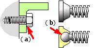
- the under-surface of a screw head which is being tightened by a spanner;
- the spherical seating of a G-clamp screw in the stationary self-aligning anvil.
There are always three major components in practical applications of the screw thread mechanism :
Clearly
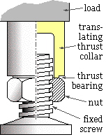 there is relative motion in the thrust bearing, and also between the nut and the screw - and where there is relative motion there is friction. We now examine the role of friction since it dominates the behaviour of the mechanism unless special ( read 'expensive' ) means are taken to minimise its effects. When considering friction it doesn't matter which component rotates and which is stationary - it's the relative motion which is important. We shall therefore analyse the jack shown here to deduce the general effect of friction on screw thread behaviour.
The jack's screw is fixed; the nut is rotated by a spanner and translates vertically. The thrust collar's only motion is vertical translation as it is prevented from rotating by contact with the load, one corner only of which is pictured. Since there is relative rotation between contacting nut and collar, the contacting surface assumes the role of thrust bearing.
The
 nut shown here in plan is in contact with three bodies :
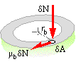
Consider the thrust bearing first. We shall assume that the contact surface of area A is in the form of a narrow annulus of mean radius rb on which the uniform pressure is W/A, where W is the load supported by the mechanism. If the coefficient of friction in the bearing is μb then the torque exerted by the frictional force on an area element δA is δTb = μb δN rb = μb rb ( W/A ) δA. Integrating over all the contact area
( ii) Tb = W μb rb
Consider now the thread which is square, of mean radius rm and lead angle λ. The nut engages the screw with friction coefficient μ corresponding to a friction angle φ = arctan μ. The static and kinetic coefficients of friction are taken to be essentially equal for this preliminary analysis.
We wish to find the torque Tt which must be exerted on the nut to offset thread friction and maintain the load W in equilibrium - that is either static or moving at constant speed. A torque which tends to raise the load is reckoned positive; a negative torque is one which tends to lower the load.
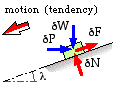
A small element of the nut is shown below sliding or about to slide on the inclined ramp of the thread, this motion being either up or down the thread. Both motion directions are sketched. δP is the small force on the element due to the torque, and the element supports a small part of the load δW. The contact force components are the normal and friction forces, δN and δF - the latter opposing motion or motion tendency.
| The nut element free body requires for equilibrium . . . | 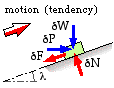
| 
| |||
| normal to plane : | δN = δP sinλ + δW cosλ | ||||
| parallel to plane : | δF = δP cosλ - δW sinλ | δF = - δP cosλ + δW sinλ | |||
| If the element is moving, or on the point of motion, then δF = μ δN and so | |||||
| eliminating δF, δN : | δP = δW tan ( λ + φ ) | δP = δW tan ( λ - φ ) | |||
| The total torque Tt is the sum Σ rmδP over all the identical nut elements, ie. | |||||
| ( iii) | . . . . if motion (tendency) is | Tt = W rm tan ( λ + φ )
upwards | Tt = W rm tan ( λ - φ )
downwards | ||
The upward tightening torque from ( iii) is plotted here against friction coeffficient for a lead angle, λ = 0.25 ( 14.3o ).
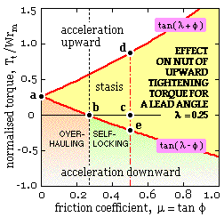
When there is negligible thread friction ( φ = 0 ) then Tt /Wrm = tanλ = 0.255, the point a.
The equilibrium line a-d corresponds to incipient motion up the thread; the equilibrium line a-b-e corresponds to incipient motion down the thread. The area between these lines represents stasis ( δF < μ δN ); the areas beyond the lines correspond to non-equilibrium, ie. to acceleration - though it should be realised that only thread friction is being considered at this point.
Consider what happens if the coefficient of friction is 0.5 for example. Before any torque is applied ( Tt = 0 ) the nut is at rest, point c. The torque is thereafter increased until at d the nut breaks away and rotates up the thread at constant velocity. If the torque were to increase further then the nut would accelerate.
If however at c the torque were to increase in a negative sense - to 'undo' the nut, assisted by the load - then when point e was reached the nut would break away and move down the thread at uniform speed. Any further increase of torque in the negative sense would lead to downward acceleration.
The point b is significant. It corresponds to the critical coefficient of friction for the lead concerned, μc = tanλ, at which the nut is on the point of moving down the thread of its own volition without any torque applied ( Tt = 0 ). Further, if . . .
| μ>μc | then the thread is self-locking in that the nut cannot undo by itself, it needs to be unscrewed by a definite negative torque; or |
| μ<μc | then the thread is overhauling in that the nut will unscrew by itself under the action of the load unless prevented by a positive tightening torque. |
|
|
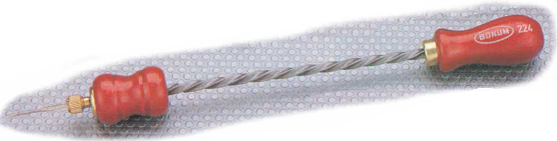
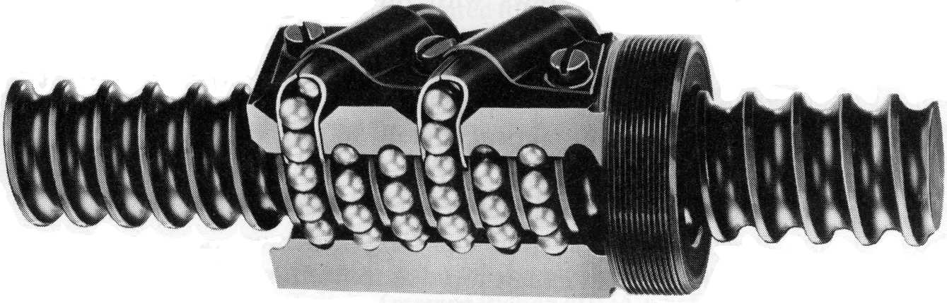 than any actual coefficient likely to be encountered. Sensitive linear actuators may incorporate recirculating ball screws such as that illustrated on the left to reduce thread friction to levels which go hand- in- hand with overhauling.
Efficiency is important in rotary/ linear motion transformation such as provided by power screws. Whilst acting against a load, the efficiency of a screw thread alone ( ie. neglecting the thrust bearing ) is :
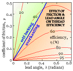
η = Wfor a given Tt / Wfor the same Tt without friction
= tan λ / tan( λ + φ ) from ( iii)
The effect of lead and friction on thread efficiency is plotted here - as expected, high efficiencies demand very low friction. Also shown is the line of critical friction.
Coefficients of friction around 0.1 to 0.2 may be expected for common materials under conditions of ordinary service and lubrication - steel on steel for fasteners, and steel on bronze or cast iron in the case of power screws. Special coatings and surface treatments can reduce friction significantly. Vibration also reduces friction and can cause fasteners to unloosen unless locked as mentioned above.
Lead angles around 3o are typical of single start power screws which are therefore somewhat inefficient - this is one reason for multiple start screws with their associated large leads.
From ( i), ( ii) and ( iii) the total torque necessary to raise a load W whilst overcoming thread and thrust bearing friction is :
( 2) T = W [ rm tan( λ + φ ) + μb rb ]
The foregoing analysis has been developed for square threads ( α = 0 ), but ( iii) and ( 2) may be applied with little error to Acme threads ( α = 29o ), and also to ISO Metric fasteners ( α = 60o ) provided the effect of wedging ( analogous to V-belts ) is included - thus the effective coefficient of thread friction to be used in ( 2) is μ sec( arctan( cosλ tanα/2 )), which tends to μ secα/2 for small lead angles.
| TABLE 2. STRENGTH OF STEEL BOLTS | |||||||
| class no. | 4.6 | 5.8 | 8.8 | 9.8 | 10.9 | 12.9 | |
| Su MPa | 400 | 500 | 800 | 900 | 1000 | 1200 | |
| Sy MPa | 240 | 400 | 640 | 720 | 900 | 1080 | |
| Sp MPa | 225 | 380 | 590 | 650 | 830 | 970 | |
| elong'n % | 22 | 20 | 12 | 10 | 9 | 8 | |
It is difficult to determine the yield of a full size threaded connector ( as opposed to a cylindrical test piece ) because of the different strain rates of shank, thread and runout. For this reason the proof stress rather than the yield stress is used as a criterion for failure assessment - the proof stress Sp is the largest stress which does not lead to any permanent set. The proof load of a screw made from a particular material is the maximum load the screw can withstand without permanent deformation, and is given by ( 1) as the product of stress area ( Table 1 ) and proof stress ( Table 2 ). Selection of class 12.9 should not be undertaken lightly - its high strength begets other potential problems.
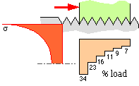
We have noted that the elastic behaviour of connected members has a significant effect upon the distribution of load between their connectors. In an elastic bolt and nut connected by a number of thread turns, the first 'thread' takes a disproportionate fraction of the total tensile load - Craddock op cit reports the load distributed among the threads as sketched here. It is clear that there is little benefit from an engagement length exceeding half-a- dozen threads. Special nuts which alleviate non-uniform load distribution are available. The variation of normal stress σ over a cross- section adjacent to the nut face ( as sketched ) is dominated by stress concentration induced by the thread root, so it is hardly surprising that bolt fractures usually occur in the exposed threads close to the nut face.

Another failure mechanism is stripping of the nut threads, which is essentially shear failure of the nut material on the cylindrical surface at the thread major diameter. Stripping of the bolt threads is a similar shear of the bolt material at the minor diameter - but this is rare. Other possible failure mechanisms, such as crushing of the nut bearing surface and dilation of a thin nut due to its riding up the thread flanks, are not critical in themselves, but contribute to other modes.
If any failure is to occur, then bolt fracture is the preferred mode. Bolt fracture is clearly discernable and often occurs whilst tightening, when torsional shear stresses ( which dissipate quickly after tightening ) are superimposed upon tensile stresses. So the operator replaces the bolt and learns to exercise care in subsequent tightening. Thread stripping on the other hand is insidious and progressive - the first thread fails putting more load onto the remaining threads, hence the second succumbs . . . and so on. When threads strip it is often difficult to separate components for fastener replacement, whereas a broken bolt requires no further separation. The consequences of a tapped hole in a car engine block being stripped by over- zealous spanner wielding is a case in point.
For a given load, bolt fracture tendency will clearly be reduced by a larger stress area ( ie. a larger bolt size ) and/or a higher class of material. Given these parameters ( load, size and bolt class ), nut stripping will be reduced by a longer nut and hence an increased cylindrical shear area, by a thicker walled nut to decrease dilation, and/or by a superior nut (property) class.
The first stage of fastener design is bolt selection - size, class and other geometric attributes. ISO Metric nuts have been dimensioned to bias any failure towards bolt fracture rather than nut stripping, on the tacit presumption that the nut class is equal to or greater than the bolt class - ie. the material of the chosen nut is at least as strong as the preselected bolt's material. It is for such reasons that regular nut lengths are about 80% of bolt size, and of the hexagonal dimensions shown in Table 1 - though there are various styles of nut which differ from these figures.