 where the material is chosen and the minimum dimensions necessary to avoid failure are calculated before the implement is later made to suit.
You are walking in the countryside when you come across a creek which is too wide to jump. Problem: How can you cross to the far side without a soaking? Applying creativity, you may come up with the following possible solutions, depending upon the circumstances :-
These and other solutions, apart from the first, require implements - ropes, trees and the like - whose failure may be through either
We may examine an implement's safety (absence of failure) by one of three approaches :-
 where the material is chosen and the minimum dimensions necessary to avoid failure are calculated before the implement is later made to suit.
An implement in mechanical engineering is more complex than those above, and requires careful design to ensure that everyone who is associated with it is satisfied with it. A well designed artefact is cheap to manufacture, and is easy and safe to use and to maintain, among other things.
Implement safety can of course be assured by building a physical model and testing it, but this is usually uneconomical and so one of the major aspects of this course is to demonstrate the formation of mathematical models of various mechanical components - bits and pieces such as shafts, brakes, welds, bearings and the like, which are assembled into machines for transforming mechanical power outside the human performance envelope. These models may be analysed to predict the prototypes' behaviour and safety before they are built, and in conjunction with sketches enable component design to be carried out.
It must be appreciated that the techniques of (mathematical) model building which are introduced in the context of one particular component are usually applicable to many other components which cannot be considered in the course, and therefore the course emphasis is as much on how we arrive at a result as on what that result is.
In this chapter we trace the steps necessary for setting up the mathematical model (the design equation) of any component and derive the equation for one of the most common components in mechanical engineering - the round shaft. Static failure only is considered at this stage, but the same approach is used later in the course for other failure mechanisms such as fatigue and fracture.
A component subjected to a solitary load will be considered in the first instance. This load is interpreted in the context of the component's nature and duty - thus load usually implies a transverse force in the case of a beam component, or a longitudinal compressive force in a column, or a torque in the case of a shaft, or a pressure in a fluid containment vessel, and so on.
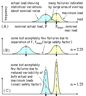
There are two completely different manifestations of the load, which have important consequences for the component :
Clearly a component is safe only if the actual load applied to the component does not exceed the component's inherent maximum sustainable load. The degree of safety is usually expressed by the safety factor, n :-
( 1 ) n = maximum load / actual load = Fmax / F
. . . . and it follows that :
 The safety factor is usually expressed as a ratio of nominal loads. A higher value of the safety factor seems to indicate a safer component - however this is not necessarily the case as the inevitable variations must be kept in mind.
When an assemblage of components is subjected to a single load, the assembly's safety factor is the smallest of the component safety factors - 'a chain is only as strong as its weakest link'. If a component or an assemblage is subjected to a number of different simultaneous loads, then the concept of a single safety factor may be inappropriate - but nevertheless all potential failure mechanisms must be investigated when deciding whether an implement is safe to use or not.
IF - and only IF - the stress in a component is proportional to the actual load on the component, then the safety factor may be interpreted also as a stress ratio :-
| ( 1a ) n = S / σ | where S is the strength of the component's material, and
σ is the stress in the component due to the actual load, F. |
Such an interpretation is evidently inapplicable to assemblages. Stresses are proportional to load for the majority of practical elements, so we usually assume that the stress ratio interpretation ( 1a) applies. But this is NOT the case with some not uncommon failure mechanisms (examined later) such as buckling and Hertzian contact - in these cases we must fall back on the fundamental load interpretation ( 1).
The strength of a material is the maximum stress it can withstand without failure; it is obtained from a tensile test on a specimen of the material. Common metals follow stress-strain relations of the forms illustrated :

|
Let us derive a design equation for the simplest of all components ![]() - the tensile bar.
- the tensile bar.
The bar's cross-sectional area is A, it is subjected to a tensile force P and the strength of its material is S - which may be the ultimate if fracture is important, or the yield if the material is ductile and excessive deformation is relevant.
Assuming uniform stress across the cross-section, the maximum load that the component can sustain occurs when the stress σ reaches the material strength, and is Pmax = A.S - this expression when combined with ( 1) leads to the design equation for direct normal stress, namely :-
( 1b ) n P = A S
The design equation embodies conveniently and directly the four aspects mentioned previously - safety, load, dimensions and material (strength). The equation may be used either :
Equation ( 1b) applies also to compressive loading, however components in compression are usually more likely to fail by buckling than by any strength limitation being exceeded. Buckling (ie. geometric instability) is dictated as much by the component's overall geometry as by the inherent strength of the component's material. A cardboard tube can withstand a larger compressive load than a steel wire. The design equation for buckling is derived in a later chapter.
Suitable nominal factors of safety for use in elementary design work are as follows :
| SUGGESTED SAFETY (DESIGN) FACTORS FOR ELEMENTARY WORK | ||
| based on yield strength - according to Juvinall & Marshek op cit. | ||
| 1 | 1.25 - 1.5 | for exceptionally reliable materials used under controllable conditions and subjected to loads and stresses that can be determined with certainty - used almost invariably where low weight is a particularly important consideration |
| 2 | 1.5 - 2 | for well-known materials under reasonably constant environmental conditions, subjected to loads and stresses that can be determined readily. |
| 3 | 2 - 2.5 | for average materials operated in ordinary environments and subjected to loads and stresses that can be determined. |
| 4 | 2.5 - 3 | for less tried materials or for brittle materials under average conditions of environment, load and stress. |
| 5 | 3 - 4 | for untried materials used under average conditions of environment, load and stress. |
| 6 | 3 - 4 | should also be used with better-known materials that are to be used in uncertain environments or subject to uncertain stresses. |
| 7 | Repeated loads : the factors established in items 1 to 6 are acceptable but must be applied to the endurance limit (ie. a fatigue strength ) rather than to the yield strength of the material. | |
| 8 | Impact forces : the factors given in items 3 to 6 are acceptable, but an impact factor (the above dynamic magnification factor ) should be included. | |
| 9 | Brittle materials : where the ultimate strength is used as the theoretical maximum, the factors presented in items 1 to 6 should be approximately doubled. | |
| 10 | Where higher factors might appear desirable, a more thorough analysis of the problem should be undertaken before deciding on their use. | |
Design factors are increased also when the consequences of failure - economic, social, environmental or political - are serious. For example, a local manufacturer of processing machinery destined for the headwaters of the Yangtze River, doubled the size of every motor predicted by the design process because of the delay in providing replacements if failure should occur due to overload. This is another example of the designer having to foresee the whole future life of an artefact.
The tensile component is the simplest of all machine members. Investigation into the safety of a more complex component involves searching over all elements of the component (ie. over all locations in the component) to find the weakest link - the element with the smallest safety factor. In practice for a given component only a few elements are potentially critical, so an intelligent search is not necessarily protracted. At each element, safety is assessed by means of the following general approach :-
These four steps will be examined individually in the following sections, and will be examplified in setting up the design equation for a very common component - a shaft of circular cross-section subjected to simultaneous bending and torsion.
But before embarking on this and writing down stress equations such as σ = P/A, we've got to appreciate the limitations of such mathematical models - we must be able to visualise qualitatively how stresses vary throughout a body and to appreciate the concept of
 stress concentration.
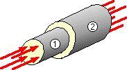
For example consider equation ( 1b) applied to the assembly comprising two short coaxial bars, 1 and 2, of cross-sectional areas 100 & 200 sq.mm and strengths 600 & 400 MPa respectively ( recall that 1 MPa is equivalent to 1 N/sq.mm).
The assembly is compressed by 50 kN distributed uniformly over each end.
Is the assembly safe or unsafe ?
This example illustrates conclusively the need to visualise qualitatively how stresses vary throughout a body and to appreciate the concept of stress concentration - let's see how we go about this . . . .