|
| ||
| A | rotary cement kiln | |
| B | container ship gas turbine | |
| C | electric power generator | |
| D | diesel engine on ferry | |
| E | caterpillar | |
| F | windmill | |
| G | refrigeration compressor | |
| H | Volvo 340 automobile | |
| I | washing machine | |
| J | windscreen wiper motor | |
| K | hand power tool | |
| L | truck turbocharger | |
| M | timer clock | |
| N | electric razor | |
| O | gyroscope | |
| P | recording cylinder | |
| Q | dentist's drill | |
As has been noted, speed reducers are employed almost invariably to amplify torque rather than to reduce speed. The two most common speed reduction mechanisms in industry are belts (usually V-belts) and gears - though chains, hydrostatic transmissions or other drives may be used. The factors other than cost which must be borne in mind when choosing a reducer are listed here -
 however shock absorption capacity, distance between shaft centres, accuracy required of shafts and mountings, tolerable vibration levels and so on may also need to be considered.
The efficiencies of belts are generally less than those of gears - that is why belts are not found in the main drive train of road vehicles where fuel economy is critical.
The diagram below compares the kinematics and kinetics of a pair of mating spur gears with those of a belt wrapped around two pulleys. The gears are represented by their pitch cylinders which roll without slip on one another, slip being prevented by the positive drive - ie. by the meshing teeth.
 The transfer of power between gears is enabled by the normal action/reaction force at the tooth contact - or more particularly by the tangential component of this force, Ft, whose moment about the centre of each free body equilibrates the shaft torque T ( assuming constant velocity ). Friction plays only a minor role - inescapable and deleterious but subsidiary nonetheless.
The transfer of power in a belt drive on the other hand relies critically on friction. The tensions Fmin & Fmax in the two strands ( the nominally straight parts of the belt not in contact with the pulleys ) cause a normal pressure over the belt- pulley contact, and it is the corresponding distributed friction whose moment about the pulley centre equilibrates the shaft torque T - provided gross slip of the belt on the pulley surface does not occur due to friction breakaway.
Ideally, for gears and for belts, the speed reduction ratio and the torque amplification ratio are each equal to the radius ratio, so that the output power equals the input power and the efficiency is 100%. The speed ratio across a real pair of gears always equals the ideal ratio because of the positive drive, however sliding friction results in a torque ratio which is less than ideal. A real belt drive is just the opposite - the torque ratio equals the ideal ratio ( as may be seen from the free bodies ), but creep results in the speed ratio being less than ideal. Creep - not to be confused with gross slip - is due to belt elements changing length as they travel between Fmin & Fmax, and since the pulley is rigid then there must be relative motion between belt element and pulley.
Since power equals the product of torque and (angular) speed, the consequence of the foregoing is that efficiencies of real gears and belts are less than 100%.
Some of the many forms of belt are introduced below.
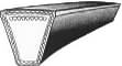
 Classical banded ( ie. covered ) V-belts comprise cord tensile members located at
 the pitchline, embedded in a relatively soft matrix which is encased in a wear resistant cover.
The wedging action of a V-belt in a pulley groove results in a drive which is more compact than a flat belt drive, but short centre V-belt drives are not conducive to shock absorption.
the pitchline, embedded in a relatively soft matrix which is encased in a wear resistant cover.
The wedging action of a V-belt in a pulley groove results in a drive which is more compact than a flat belt drive, but short centre V-belt drives are not conducive to shock absorption.
|
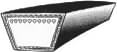
 Wedge belts are narrower and thus lighter than V-belts. Centrifugal effects which reduce belt-pulley contact pressure and hence frictional torque are therefore not so deleterious in wedge belt drives as they are in V-belt drives.
|
 Modern materials allow cut belts to dispense with a separate cover. The belt illustrated also incorporates slots on the underside known as cogging which alleviate deleterious bending stresses as the belt is forced to conform to pulley curvature. Cogging should not be confused with the teeth on . . . .
|
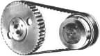 Synchronous or timing belt drives are positive rather than friction drives as they rely on gear- like teeth on pulley and belt enabled by modern materials and manufactureing methods. They are mentioned here only for completeness - we shall not examine them further.
|
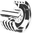 If a single V-belt is inadequate for power transmission then multiple belts and corresponding multi- grooved pulleys are necessary - this pulley is equipped with a tapered bush for axle clamping without the stress concentration associated with a key.
 The rather extreme short-centre drive on the left illustrates a problem with multiple belts - how to ensure equitable load sharing between flexible belts whose as-manufactured dimensional tolerances are significanty looser than those of machined components for example.
Two types of belt for avoiding mismatched lengths are shown : 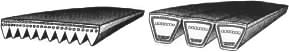
|
 Each component of a V-belt performs a particular function. The main load- carrying elements are the tensile members, often in the form of longitudinally stiff rayon cords located near the centroidal axis of the belt's cross-section, embedded in a relatively soft elastomeric matrix whose main purpose is to channel the load from the contacts with the groove sides into the tensile members.
The groove semi-angle lies usually in the range 17o ≤ β ≤ 19o. It should be noted that there is a gap ie. no contact at the bottom of the groove. Flat belts may be regarded as particular cases of V-belts in which β = 90o. |
As the belts are endless, only certain discrete standard pitch lengths are manufactured. The power demand very often necessitates a number of matched belts on multi-grooved pulleys, as illustrated above.
Discrete dimensions apply also to off- the- shelf pulleys, which are available only with certain recommended pitch diameters and number of grooves. A special pulley may be manufactured of course - but would cost more than a mass- produced commercial product. A pulley is referred to by its pitch diameter - other dimensions including its OD are available from suppliers' manuals which should be consulted also for local availability.
 A typical V-belt drive is illustrated. The effective (or pitch) diameter of the small driveR pulley is D1 ; that of the large driveN pulley is D2 .
Before the drive starts to rotate and transmit power, an initial tension Fo is produced in both belt strands by the shafts being pulled apart and then locked (eg. by a motor on slide rails or by other means).
Drive commences by the power source applying a clockwise (say) torque T1 to the shaft of the small driveR pulley, causing it to rotate clockwise at a steady speed n1 (rev/s). The tension in the 'tight' upper straight strand will then exceed Fo while the tension in the 'slack' lower strand will become less than Fo - this tension difference applies a torque to the driveN load pulley, equilibrating the load torque T2 while the pulley rotates at uniform speed n2 , also clockwise. Neglecting creep:
( 1 ) v = π D1 n1 = π D2 n2 ; speed ratio, R = n1 / n2 = D2 / D1 ≥ 1
where the belt speed, v, is limited to 30 m/s for the usual cast iron pulley material, though higher speeds can be achieved with more expensive builds. V-belts are designed for optimum performance at speeds of around 20 m/s.
In the most common V-belt drive design problem, the transmitted power and the speed of the small pulley are stipulated, together with a specified range of the speed ratio and possibly acceptable ranges of shaft centre distance and of drive life - though if the drive is designed by the methods outlined by the Code(s) then its life, though presumably commercially acceptable, cannot be evaluated.
The required drive is specified by a suitable size ( B, or γ, etc), number and length of the belt(s), and by the two pulley diameters. We therefore consider two aspects of V-belt drives :
V-belt drives are essentially short centre drives. If in drive design the centre distance C is not specified, then it should be set at around 2D1 √ (R+1) but preferably not less than D2 . Since the diameters and belt length are discrete variables so also is the theoretical centre distance, though in the absence of idlers the nominally fixed centre distance must be capable of slight variation by motor slide rails for example, to allow for belt installation and subsequent take-up (initial tightening) before rotation commences. This capability also allows for manufacturing tolerances on belt length, L. From the geometry :-
( 2a) L = π/2 ( D1 +D2 ) + 2C ( γ sinγ + cosγ ) ; where sinγ = ( D2 -D1 )/2C
This is used to find the belt length, L, for given centre distance, C (and pulley diameters). Conversely, to find the centre distance corresponding to a certain belt length, ( 2a) must be solved iteratively - a very close first approximation is given by :-
( 2b) 4 C = √[ g2 - 2( D2 - D1 )2 ] + g ; where g = L - π/2 ( D1 +D2 )
The wrap angle (or "arc of contact") on each pulley is evidently :-
( 2c) θ1 = π - 2γ ; θ2 = π + 2γ ; θ1 ≤ θ2

The power transmission capability of a drive is usually limited by the arc of contact on the small pulley, and so is reduced by large speed ratios and by short centres - eg. θ1 is only about 100o here.
Any particular cross-section of the belt traverses alternately the slack and tight strands and is subject to bending when in way of one of the pulleys, so it is clear that cyclic loading and fatigue are prevalent. Before we can look at fatigue however, we have to know the belt forces and stresses. These will depend on the belt load and speed - so let us now consider the belt kinetics.