A brake decelerates a system by transferring power from it. A clutch such as that illustrated (for the most part) accelerates a system by transferring power to it. The two devices in rotary applications are thus very similar as they both transmit torque whilst supporting a varying speed difference across them.
Brakes take a number of forms - for example a system may drive a pump or electric generator, so the pump or generator acts as a brake on the system. However the most common brakes employ friction to transform the braked system's mechanical energy irreversibly into heat
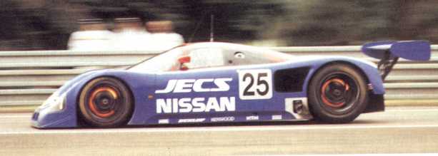 which is then transferred to the surrounding environment - see the flame generated by this sports car's brakes.
The friction mechanism is convenient since it allows force and torque to be developed between surfaces which slide over one another due to their different speeds. One of the sliding surfaces is usually metal, the other a special friction material - the lining - which is sacrificial. Wear (ie. material loss) of the lining must be catered for, and the lining usually needs to be renewed periodically.
which is then transferred to the surrounding environment - see the flame generated by this sports car's brakes.
The friction mechanism is convenient since it allows force and torque to be developed between surfaces which slide over one another due to their different speeds. One of the sliding surfaces is usually metal, the other a special friction material - the lining - which is sacrificial. Wear (ie. material loss) of the lining must be catered for, and the lining usually needs to be renewed periodically.
We examine only friction brakes in any detail here - some common embodiements are first described . . . . .
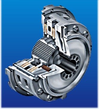
 This hydraulically actuated clutch comprises a number of discs faced with lining material which are connected alternately to input and output shafts by torque- transferring splines. The clutch is engaged by high pressure oil applied to an annular piston pressing the discs against one another while they rotate at the different speeds of the two shafts. The normal pressure between discs enable them to exert friction torque on one another which tends to equalise the two speeds.
A hydraulically activated disc brake comprises two opposing pistons each faced with a pad of lining material. When the hydraulic pressure is increased the pads are forced against the rotating metal friction disc, exerting a normal force at each contact. The two normal forces cancel one another axially but cause additive tangential friction forces which oppose the disc's motion and decelerate it.
A band brake consists of a flexible band faced with friction material bearing on the periphery of a drum which may rotate in either direction.
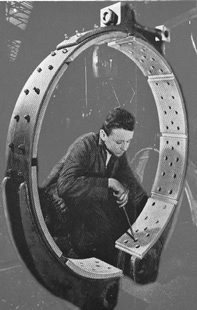
The actuation force P is applied to the band's extremities through an actuation linkage such as the cranked lever illustrated. Tension build-up in the band is identical to that in a stationary flat belt.
The band cross-section shows lining material riveted to the band. Allowance for lining wear is provided - when the rivets start to rub on the drum they are drilled out prior to new linings being riveted to the band.
The band brake on the left is destined for a fishing trawler winch.
These are external rigid shoe brakes - rigid because the shoes with attached linings are rigidly connected to the pivoted posts; external because they lie outside the rotating drum. An actuation linkage distributes the actuation force to the posts thereby causing them both to rotate towards the drum - the linings thus contract around the drum and develop a friction braking torque.
The RH brake features improved hinge locations and integral posts/shoes.
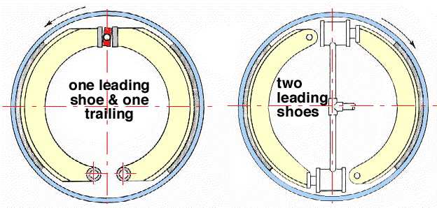
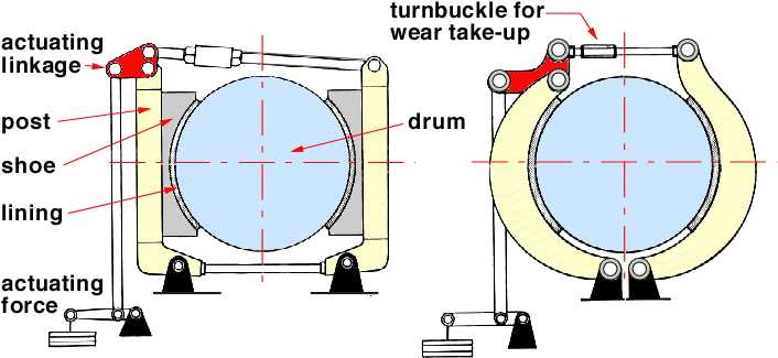
The two hydraulically actuated rigid shoe brakes here are located internal to the drum. The LH brake incorporates a rotating cam which causes the shoes to expand and the linings to bear on the surrounding drum. The RH brake features two leading shoes, enabled by an individual (and more expensive) hydraulic cylinder and piston for each shoe.The terms leading and trailing are explained below.
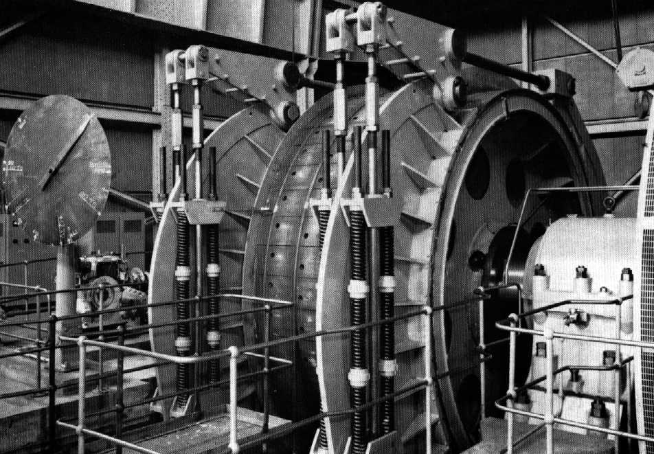
These rigid external shoe brakes act on the rope drum of a mine (cage) winder. The arrangement is fail-safe as an electric solenoid disengages the brake to allow motion, but in the event of power failure the brakes are engaged automatically by the large springs visible at the sides of the drum.
Visible in the photograph are the actuation mechanisms with wear-compensating turnbuckles, the electric drive motor on the right, and the cage level indicator on the left.
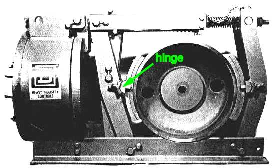
This is a hinged shoe brake - the shoes are hinged to the posts. As wear proceeds the extra degree of freedom allows the linings to conform more closely to the drum than would be the case with rigid shoes. This permits the linings to act more effectively and reduces the need for wear adjustment.
The commercial unit comes complete with actuating solenoid.
About 5% of the heat generated at the sliding interface of a friction brake must be transferred through the lining to the surrounding environment without allowing the lining to reach excessive temperatures, since high temperatures lead to hot spots and distortion, to fade (the fall-off in friction coefficient) or, worse, to degradation and charring of the lining which often incoporates organic constituents. Thorough design of a brake therefore requires a detailed transient thermal analysis of the interplay between heat generated by friction, heat transferred through the lining via the surrounding metalwork to the environment, and the instantaneous temperature of the lining surface.
Brake design investigations generally proceed along the following lines :
| - | The braked system is first examined to find out the required brake capacity, that is the torque and average power developed over the braking period. |
| - | The brake is then either selected from a commercially available range or designed from scratch. In the latter case, conservative rather than optimum brake sizing may be based upon power densities which experience has shown to be acceptable, thus avoiding the difficulties associated with heat transfer appraisal. |
| - | Analysis of the actuating mechanism is necessary to disclose the actuation requirements, brake sensitivity, bearing loads and the like. |
The braked system must be analysed to throw light on its braking requirements. Analysis requires knowledge of
| - | the system's total energy ( comprising eg. kinetic, gravitational and elastic potential ) initially, ie. before braking |
| - | the system's final total energy ie. after braking |
| - | the initial and final velocities of the brake drum |
| - | the desired braking period Δt, or alternatively the corresponding rotation of the drum Δθ |
| - | the life of the brake lining would also be specified or estimated by the designer. |
During deceleration, the system is subjected to the essentially constant torque T exerted by the brake, and in the usual situation this constancy implies constant deceleration too. The elementary equations of constant rotational deceleration apply, thus when the brake drum is brought to rest from an initial speed ωo :-
( 1 ) deceleration = ωo2/ 2 Δθ = ωo/Δt ; ωm = ωo/2 = Δθ/Δt
where ωm is the mean drum speed over the deceleration period.
Application of the work/energy principle to the system enables the torque exerted by the brake and the work done by the brake, U, to be calculated from :-
( 2 ) U = ΔE = T Δθ
where ΔE is the loss of system total energy which is absorbed by the brake during deceleration, transformed into heat, and eventually dissipated.
The mean rate of power transformation by the brake over the braking period is :-
( 3 ) Pm = T ωm = U / Δt
which forms a basis for the selection or the design of the necessary brake.
The choice of lining material for a given application is based upon criteria such as the expected coefficient of friction, fade resistance, wear resistance, ease of attachment, rigidity/formability, cost, abrasive tendencies on drum, etc.
 Non-asbestos linings generally consist of three components - metal fibres for strength, modifiers to improve heat conduction, and a phenolic matrix to bind everything together.
Linings are attached to shoes either by soft countersunk rivets or by bonding, though set-screws and proprietary fixings may be used in the larger sizes.
In order to withstand the inherent abrasion, mating surfaces should be ferrous with a hardness of at least 150 BHN, or 200 if the duty is heavy. Fine grain high tensile pearlitic iron is generally suitable. The interested reader should refer to manufacturers' publications for further information.
Having ascertained the braking requirements from the system dynamics, we now wish to form some idea of the leading dimensions of a suitable brake.
Practically achievable power density limitations apply to brakes as they do to other mechanical plant such as engines and heat exchangers. For a given size of brake there is a limit to the mechanical power that can be transformed into heat and dissipated without lining temperatures reaching damaging levels. Brake size is characterised by lining contact area, A, so denoting this maximum safe power density as Rp we have, for a reasonable lining life :-
( 4 ) Pm /A ≤ ( Pm /A )critical ≡ Rp (kW/m2)
Experience suggests the following values of Rp for various types of brake in different applications.
| TYPICAL VALUES OF Rp ( kW/m2 ) | |||||||
| type of duty | cooling conditions | typical applications | spot disc brakes | drum brakes | cone clutches | plate brakes & clutches | |
| Intermittent duty or infrequent full duty applications | Time between applications permits assembly to cool to ambient prior to actuation. | Emergency and safety brakes, safety and torque-limiting clutches. | 6000 | 1800 | 800 | 600 | |
| Normal intermittent | Some cooling between applications, but temperature builds up to a moderate level over a period of time. | All general duty applications - winding engines, cranes, winches and lifts. | 2400 | 600 | 400 | 240 | |
| Heavy frequent duty where life is critical. | Frequency of applications too high to permit appreciable cooling between applications. | Presses, drop stamps, excavators and haulage gear. | 1200 | 300 | 240 | 120 | |
| Typical lining pressure range ( kPa ) | 350-1750 | 70-700 | 70-350 | 70-350 | |||
An alternative brake rating procedure is based upon the product of average pressure, pm, over the lining contact area and the mean rubbing speed, vm, during deceleration. This procedure requires knowledge of the coefficient of friction, μ, so it is less useful than ( 4) and is mentioned only because it is commonly used - we shall persevere with ( 4). However if F is the lining contact resultant then :-
( i) pm vm = ( Fnormal/A ) vm = ( Ftangential/μA ) vm = Pm/μA = Rp/μ
which may be used analogously to ( 4) to determine the necessary minimum lining area necessary to dissipate a given power if μ is known.
If a drum brake has to be designed for a particular system (rather than chosen from an available range) then the salient brake dimensions may be estimated from the necessary lining area, A, together with a drum diameter- to- lining width ratio somewhere between 3:1 and 10:1, and an angular extent of 100o say for each of the two shoes.
The lining is sacrificial - it is worn away. The necessary thickness of the lining is therefore dictated by the volume of material lost - this in turn is the product of the total energy dissipated by the lining throughout its life, and the specific wear rate Rw (volume sacrificed per unit energy dissipated) which is a material property and strongly temperature dependent as may be seen from the graph above for Ferodo AM 2. This temperature dependence may be expressed as :-
( ii) Rw ≅ Rwo exp ( ( lining temperature oC / To ) n )
where Rwo , To and n are constant material properties.
The following example demonstrates use of the foregoing, however in practice wear rate is difficult to assess since a thermal analysis is needed to predict the lining temperature.
This example demonstrates how a brake and its lining may be sized for a given duty when the lining properties and operating temperature are known.
The final aspect of drum brakes which we will investigate involves the analysis of a given brake in order to correlate the input actuation with the output braking torque. The analysis will also evaluate loads throughout the brake - loads such as the drum reaction, the knowledge of which is necessary for the design of drum shaft and bearings.
So . . . . on to brake analysis.