BUCKLING
When a structure ( subjected usually to compression ) undergoes visibly large displacements transverse to the load then it is said to buckle. Buckling may be demonstrated by pressing the opposite edges of a flat sheet of cardboard towards one another. For small loads the process is elastic since buckling displacements disappear when the load is removed.
Local buckling of plates or shells is indicated by the growth of bulges, waves or ripples, and is commonly encountered in the component plates of thin structural members.
Buckling proceeds in manner which may be either :
|
| stable -
| in which case displacements increase in a controlled fashion as loads are increased, ie. the structure's ability to sustain loads is maintained, or
|
|
| unstable -
| in which case deformations increase instantaneously, the load carrying capacity nose- dives and the structure collapses catastrophically.
|
Neutral equilibrium is also a theoretical possibility during buckling - this is characterised by deformation increase without change in load.
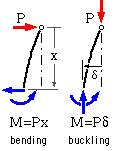
Buckling and bending are similar in that they both involve bending moments. In bending these moments are substantially independent of the resulting deflections, whereas in buckling the moments and deflections are mutually inter-dependent - so moments, deflections and stresses are not proportional to loads.
If buckling deflections become too large then the structure fails - this is a geometric consideration, completely divorced from any material strength consideration. If a component or part thereof is prone to buckling then its design must satisfy both strength and buckling safety constraints - that is why we now examine the subject of buckling.
Buckling has become more of a problem in recent years since the use of high strength material requires less material for load support - structures and components have become generally more slender and buckle- prone. This trend has continued throughout technological history, as is demonstrated by bridges in the following sequence :
 The Pont du Gard in Provence was completed by the Romans in the first century AD as part of a 50km aqueduct to convey water from a spring at Uzès to the garrison town of Nemausus (Nimes). The bridge is constructed from limestone blocks fitted together without mortar and secured with iron clamps. The three tiered structure avoids the need for long compressive members. ( source Art images for College Teaching )
|
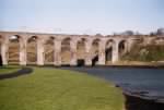 The Royal Border Bridge, Berwick upon Tweed, was built by Robert Stephenson whose father George built the Stockton and Darlington Railway (the first public railway) in 1825. Opened in 1850, the bridge continues today as an important link in the busy King's Cross (London) - Edinburgh line. The increased slenderness of the columns compared to the Pont du Gard reflect technological improvements over many centuries. ( source FreeFoto.com )
|
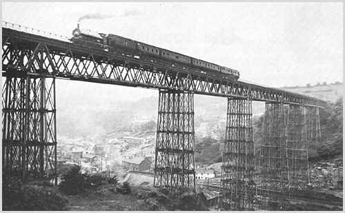
 The Crymlyn Viaduct over the Ebbw Alley opened in 1857 as Welsh coal mining expanded. It was constructed of wrought and cast iron, and remained the highest railway viaduct in the UK until its closure in 1964 due to increased locomotive weights (1908 photo). The advance from masonary to the slender metal compressive members which make up each column requires substantial bracing to prevent buckling ( source John Croeso )
|
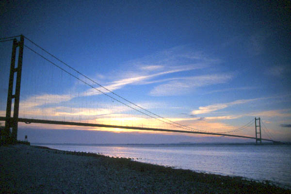
 The Humber road bridge, opened in 1981, comprises a continuously welded closed box road deck suspended from catenary cables supported on reinforced concrete towers. Suspension bridges eliminate the need for struts other than the two towers, however avoiding buckles in other slender components becomes an issue ( source FreeFoto.com )
|
|
Buckling of thin-walled structures
A thin-walled structure is made from a material whose thickness is much less than other structural dimensions. Into this category fall plate assemblies, common hot- and cold- formed structural sections, tubes and cylinders, and many bridge and aeroplane structures.
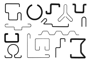
Cold- formed sections such as those illustrated are increasingly supplanting traditional hot- rolled I-beams and channels. They are particularly prone to buckling and in general must be designed against several different types of buckling.
It is not difficult to visualise what can happen if a beam is made from such a cold- rolled channel section. One flange is in substantial compression and may therefore buckle locally at a low stress ( ie. much less than yield ) thus reducing the load capacity of the beam as a whole. Buckling rather than strength considerations thus dictate the beam's performance.
Let us now look at typical examples of buckling.
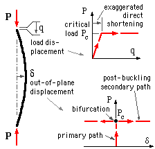
The slender elastic pin-ended column is the protoype for most buckling studies. It was examined first by Euler in the 18th century. The model assumes perfection - the column is perfectly straight prior to loading, and the load when applied is perfectly coaxial with the column.
The behaviour of a buckling system is reflected in the shape of its load- displacement curve - referred to as the equilibrium path. The lateral or 'out-of-plane' displacement, δ, is preferred to the load displacement, q, in this context since it is more descriptive of buckling.
Nothing is visible when the load on a perfect column first increases from zero - the column is stable, there is no buckling, and no out- of- plane displacement. The P-δ equilibrium path is thus characterised by a vertical segment - the primary path - which lasts until the increasing load reaches the critical Euler load Pc = π2 EImin/L2 a constant characteristic of the column ( for a derivation of this, see below or Timoshenko & Gere op cit. for example ).
When the load reaches the Euler load, buckling suddenly takes place without any further load increase, and lateral deflections δ grow instanteously in either equally probable direction. After buckling therefore, the equilibrium path bifurcates into two symmetric secondary paths as illustrated. Clearly the critical Euler load limits the column's safe load capacity.
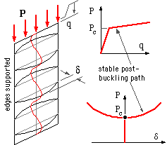 Local buckling of an edge-supported thin plate does not necessarily lead to total collapse as in the case of columns, since plates can generally withstand loads greater than critical. However the P-q curve illustrates plates' greatly reduced stiffness after buckling, so plates cannot be used in the post- buckling region unless the behaviour in that region is known with confidence.
It should be emphasised that the knee in the P-q curve is unrelated to any elastic- plastic yield transition; the systems being discussed are totally elastic. The knee is an effect of overall geometric rather than material instability.
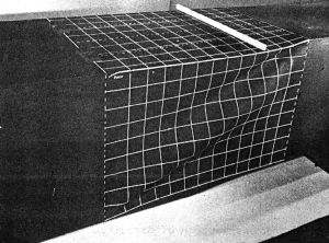
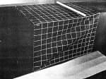 This photograph illustrates local buckling of a model box girder constructed from thin plates, not unlike the road deck of the Humber bridge above.
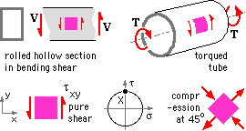
Inclined striations are caused by shear loading in the web of a beam or in a torqued tube giving rise to compressive buckling stresses at 45o to the longitudinal direction as predicted by Mohr's circle.
|
 The behaviour of a compressed shell after buckling is quite different to that of a plate; in this case an unstable ( negative ) stiffness is accompanied by a sudden reduction of load capacity.
Since the displacements are uncontrolled in most practical systems, shells behave in a snap- buckling mode - ie. as an increasing load reaches the bifurcation point, the cylinder
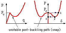 must undergo an instantaneous increase in deflection ( "snap" ) to the point 1 in order to accomodate the increasing load. A subsequent decrease in load is accomodated by a corresponding decrease in buckling deflection until the point 2 is reached whereupon the structure again snaps instantaneously - this time back to the point 3 on the primary path.
Clearly this behaviour makes it imperative in design to apply large safety factors to the theoretical buckling loads of compressed cylinders.
|
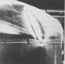
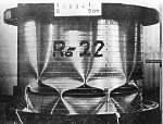
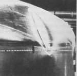
| It has been noted that a pressure vessel head is subjected to a compressive hoop stress at its junction with the cylinder.
The two photographs here (from Ramm op cit) show both inward and outward buckles arising from this compression in the torispherical heads of internally pressurised 3 m diameter stainless steel vessels.
|
| 
|
|
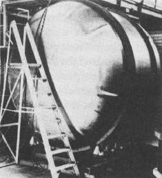
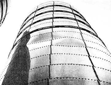
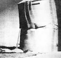
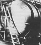
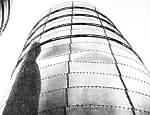
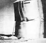
| Longitudinal stresses in a vertical cylinder may also promote buckling as these two photographs illustrate (from Rhodes & Walker op cit).
Warning of impending failure of the 7.3 m diameter vitreous enamelled silo on the left is provided by the visible buckles.
Grain pours out of the buckled bin on the right - the ladder gives an idea of the bin size.
|
| 
|
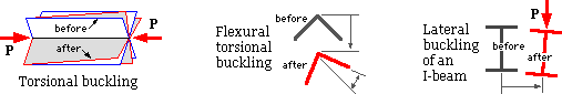
Torsional buckling of columns can arise when a section under compression is very weak in torsion, and leads to the column rotating about the force axis.
More commonly, where the section does not possess two axes of symmetry as in the case of an angle section, this rotation is accompanied by bending and is known as flexural torsional buckling.
Lateral buckling of beams is possible when a beam is stiff in the bending plane but weak in the transverse plane and in torsion, as is the I-beam of the sketch.
It often happens that a system is prone to buckling in various modes. These usually interact to reduce the load capacity of the system compared to that under
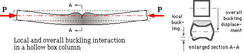 the buckling modes individually. An example of mode interaction is the thin box section which develops local buckles at an early stage of loading, as shown greatly exaggerated here.
The behaviour of the column is influenced by these local buckles, and gross column buckle will occur at a load much less than the ideal Euler load. The Steel Structures Code, AS 1250 op cit. sets out rules for the avoidance of mode interaction in large components, and its guidelines should be followed in design.
|
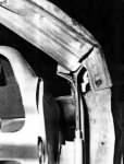
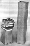
| Buckling has mixed blessings in automotive applications.
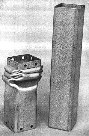
The photograph on the left illustrates how local buckling of a car's thin-walled A-pillar dramatically reduces passenger cell integrity in the event of roll-over.
Conversely, the energy absorbed by plastic buckling can reduce significantly the injuries suffered by a vehicle's occupants in the event of a crash. The energy absorption capability of thin- walled sections is demonstrated clearly by the experiment photographed on the right. (from Murray op cit)
|
| 
|
The detailed analysis of most practical buckle-prone structures is too complex mathematically to attempt here. We therefore examine instead some mechanisms which demonstrate (un)stable behaviour similar to that of structures. The mechanisms allow us to appreciate buckling behaviour and the tools used to analyse it, and to introduce the concept of imperfections which must occur in practical components and which have a relatively large effect on buckling behaviour and safety.
This work leads to the derivation of a design equation for practical columns, in which the twin failure modes of strength and geometric instability invariably interact. This interaction is apparent also in the behaviour of cracks - the subject of a later chapter.
Prediction of the plastic collapse of sub-sea pipelines is also addressed.
 Copyright 1999-2005 Douglas Wright, doug@mech.uwa.edu.au
last updated May 2005
 The Pont du Gard in Provence was completed by the Romans in the first century AD as part of a 50km aqueduct to convey water from a spring at Uzès to the garrison town of Nemausus (Nimes). The bridge is constructed from limestone blocks fitted together without mortar and secured with iron clamps. The three tiered structure avoids the need for long compressive members. ( source Art images for College Teaching )
 The Royal Border Bridge, Berwick upon Tweed, was built by Robert Stephenson whose father George built the Stockton and Darlington Railway (the first public railway) in 1825. Opened in 1850, the bridge continues today as an important link in the busy King's Cross (London) - Edinburgh line. The increased slenderness of the columns compared to the Pont du Gard reflect technological improvements over many centuries. ( source FreeFoto.com )
 The Crymlyn Viaduct over the Ebbw Alley opened in 1857 as Welsh coal mining expanded. It was constructed of wrought and cast iron, and remained the highest railway viaduct in the UK until its closure in 1964 due to increased locomotive weights (1908 photo). The advance from masonary to the slender metal compressive members which make up each column requires substantial bracing to prevent buckling ( source John Croeso )
 The Humber road bridge, opened in 1981, comprises a continuously welded closed box road deck suspended from catenary cables supported on reinforced concrete towers. Suspension bridges eliminate the need for struts other than the two towers, however avoiding buckles in other slender components becomes an issue ( source FreeFoto.com )