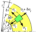
In the absence of bending and direct shear, the radial and tangential stresses are circumferentially symmetric (independent of θ) but vary with radius r. It is convenient to normalise the radius by the constant internal radius, setting :
( iii) γ ≡ ( r / ri )2 ; 1 ≤ γ ≤ γo = ( ro / ri )2 = ( Do / Di )2
where γo is a constant, representing the proportions of the cylinder.

Consider the element, defined by r, δr and δθ, and of unit width perpendicular to the sketch plane. For radial equilibrium :
σr r δθ - ( σr + δσr )( r + δr ) δθ + 2 σt δr sin(δθ/2) = 0
which, on expanding with neglect of second order terms, gives :
( iv) ( σt - σr ) δr = r δσr
As σt and σr cannot be found individually from this equilibrium equation, the problem is statically indeterminate - so compatibility and the constitutive law must be invoked. The compatibility requirement, first postulated by Lamé,
 that initially plane transverse cross-sections remain plane when loaded, implies that the axial strain, εa, is constant across the cross-section - ie. is independent of radius. With the elastic constitutive law, this may be expressed as :
E εa = σa - ν ( σt + σr ) = constant, ie. independent of r,
and since σa is itself constant and independent of r, it follows that :
( v) σt + σr = constant = 2 σm where σm is some constant, as yet undefined.
This latter compatibility/constitutive equation enables resolution of the indeterminacy. Thus, eliminating σt between ( iv) and ( v) :
δσr / ( σr - σm ) = - 2 δr / r and integrating with γ given by ( iii )
( vi) σr = σm - constant / r2 = σm - σv / γ where σv is an integration constant.
The form of the stress distribution is thus
 established but the two unknown constants σm and σv must be evaluated before the distribution is defined completely. From ( vi) and from equilibrium of elements at the inner and outer surfaces :
inside σr = σm - σv = - pi
outside σr = σm - σv /γo = - po
which may be solved for the unknown constants in terms of the known pressures :
( 2) σm = ( pi - γo po ) / ( γo - 1 ) ; σv = ( pi - po ) γo / ( γo - 1 ) and = σm + pi
Combining ( v) and ( vi), and recalling ( i), yields the final stress distribution equations :
( 3) σt = σm + σv / γ
σr = σm - σv / γ ≤ 0
σa = σm (closed) or σa = 0 (open)
by which all stress components are expressible in terms of location, r ( ie. γ ), once the constants σm and σv have been evaluated from ( 2) in terms of proportions and loading.
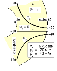
The stress variations given by ( 2) and ( 3) for a particular closed cylinder are sketched here, and the Mohr's circles corresponding to the bore ( γ = 1 ) and to some other location in the wall ( γ > 1 ) appear below - the similarity between the Mohr's circles for thick and thin cylinders is noticeable. The tangential /radial stress distribution is seen to take the form of a horn disposed symmetrically about σm and of opening radius σv at the bore, confirming the general conclusion that the bore is the critical location - as expected since curvature and stress concentration are most severe there.
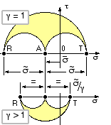
If this cylinder were ductile and the maximum shear stress failure criterion is applied, then the equivalent stress is 180 MPa at the bore and only 20 MPa at the outside - evidently the material in a thick cylinder is not used effectively throughout the wall.
The advantages of the normalised treatment used here may be appreciated by comparing ( 2) and ( 3) with the corresponding equations in the literature.
The pressures or overall proportions ( γo ) may not be known initially, in which case equations ( 3) are usually applied in the context of the problem, with σm and σv retained as unknown constants
 whose solution is sought first.
( The nomenclature should be noted here: σa is used in these Notes to represent principal stress amplitude and hence the radius of Mohr's circles - see the nomenclature explanation - however σa symbolises axial stress in cylinder theory and necessitates σv being used here to represent Mohr's circle radius. )
For the particular case of pressure po external to a solid shaft, ri = 0, both γo and γ tend to infinity, in which case ( 2) and ( 3) degenerate to :
( 3a) σt = σr = - po ie. stresses are everywhere uniformly compressive for solid shafts.
The following equations have been derived from ( 2) and ( 3) with the appropriate failure theory. The detailed proofs, left to the reader, exemplify the difficulties associated with the application logic of piecewise- defined theories such as the maximum shear stress and modified Mohr.
For DUCTILE materials the concept of equivalent stress, σe, is relevant. If the distortion energy failure theory is applied, then using ( 3) :
σe = [ {
( σt - σr )2 +
( σr - σa )2 +
( σa - σt )2
} / 2 ]1/2
= [
( σm - σa )2 +
3 ( σv / γ )2 ]1/2 where the appropriate σa is given by ( 3)
The maximum equivalent stress, defined as σ* = σemax, occurs when γ is a minimum ie. at the bore where γ = 1. Resulting design equations are therefore :
( vii) Distortion energy
OPEN σ* = [ ( pi - γo po )2 + 3 γo2 ( pi - po )2 ]1/2 / ( γo - 1 )
CLOSED σ* = √3 | pi - po | γo / ( γo - 1 )
If, on the other hand, the maximum shear stress theory is applied, it may again be shown that the maximum equivalent stress occurs at the bore, where the principals from ( 2) and ( 3) are :
σt = [ ( γo + 1 ) pi - 2 γo po ] / ( γo - 1 ) ;
σr = - pi ;
σa = [ pi - γo po ] / ( γo - 1 ) or 0
Application of the theory requires selection of the minimum and maximum principal stresses, with neglect of the intermediate, and it is apparent that σt may or may not exceed either σr or σa. It is necessary therefore to consider all feasible combinations of the principals, and this results in :
| ( viii) Maximum shear stress | ||||
| OPEN | ordered | application limits, po/pi | value of | |
| principals | minimum | maximum | ( γo - 1 ) σ* | |
| σr ≤ σa ≤ σt | 0 | ( 1 + 1/γo ) / 2 | 2 γo ( pi - po ) | |
| σr ≤ σt ≤ σa | ( 1 + 1/γo ) / 2 | 1 | ( γo - 1 ) pi | |
| σt ≤ σr ≤ σa | 1 | infinity | - ( γo + 1 ) pi + 2 γo po | |
| CLOSED | - | 0 | infinity | 2 γo | pi - po | |
BRITTLE cylinders subscribe to the modified Mohr failure theory for which the safety factor is given by the maximum of three terms, each of which is linear in the principal stresses :
1/n = max ( σmax/St ,
- σmin/Sc ,
σmax/St - (σmax+ σmin)/Sc )
where σmax, σmin = max, min ( σt, σr, σa)
The implications of this piecewise defined theory may be appreciated with reference to a closed cylinder of geometry γo = 3 in a material whose strengths are St = 200, Sc = 700 MPa.
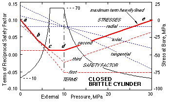
The cylinder is subjected to a constant internal pressure of 10 MPa while the external pressure increases from 0 to 30 MPa. The sketch traces the three principal stresses at the critical bore - the two extremes are the tangential and the radial (which is constant). Also shown are the three terms of the modified Mohr equation - the maximum of these comprises four linear segments a-b-c-d-e.
The tangential extreme, which is tensile initially at a, becomes progressively more compressive as the external pressure rises until at d when the pressures are identical and the stresses are all compressively equal to the pressures. In a-d the varying tangential principal is maximum while the constant radial is minimum. These roles are reversed in d-e. The three modified Mohr terms change accordingly - in a-b the first term is the maximum of the three, in b-c the third term dominates, in c-d-e the second term. As a result of the interaction between the individually simple terms the safety factor changes in a complex fashion, increasing from 10 to 70 then remaining constant before falling monotonically with further rise in external pressure. Repeating this analysis algebraically (problem #8) leads to a four-piece design equation.
An identical approach for brittle OPEN cylinders results in a similar design equation, viz :
| ( ix) Modified Mohr | value of | |||
| OPEN | ordered | application limits, po/pi | ( γo - 1 ) Suc / n | |
| principals | minimum | maximum | where m = Suc / St | |
| σr ≤ σa ≤ σt | 0 | 1/γo | [ ( γo + 1 ) pi - 2 γo po ] m | |
| " | 1/γo | ( 1 + 1/γo ) / 2 | [ ( γo + 1 ) m - 2 ] pi - 2 ( m - 1 ) γo po | |
| σr ≤ σt ≤ σa | ( 1 + 1/γo ) / 2 | 1 | ( γo - 1 ) pi | |
| σt ≤ σr ≤ σa | 1 | infinity | - ( γo + 1 ) pi + 2 γo po | |
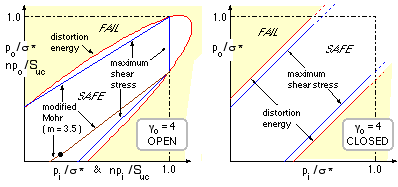
The failure loci corresponding to ( vii), ( viii), and ( ix), are illustrated for the case of γo = 4; loci for other proportions are of similar shape. The absence of upper limits for ductile closed cylinders is due to triaxiality - approximately equal principals with small shear, analogous to hydrostatic loading.
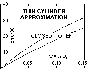
The error which arises from the use of the thin cylinder equations will now be evaluated for ductile cylinders subjected to internal pressure and subscribing to the distortion energy failure theory. Setting w = t/Di, and employing ( ii) & ( iii), the error in the maximum equivalent stress is :
The plot of these errors indicates that a thin/thick transition at say w = 0.04 corresponds to an error of about 10 %, and that the thin cylinder equations always underestimate the equivalent stress.
The design of thick cylinders is illustrated by this example.
While there may be little difference between theories in analysis situations - when equivalent stresses or safety factors are being calculated - the equations' forms often lead to substantial differences in the dimensions predicted by the theories in synthesis situations. Thus note the large difference in the diameters predicted by the thin and thick theories in part (a) of this example, and by the maximum shear stress and distortion energy ductile failure theories in parts (b) and (c).
Stress concentration at the bore of thick cylinders can lead to very wasteful use of material - see the above example with internal and external pressures of 120 and 40 MPa. It is not uncommon to be faced with a design which at first glance seems impossible - thus in the selection of a fixed bore cylinder, increasing the OD in an effort to "beef it up" merely increases γo and stress concentration, so preventing a solution from being obtained. It may be possible to choose a stronger material, however a more satisfactory solution - especially when weight is an issue - is to use a compound cylinder, which we now examine.