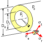
Cylinders find many applications, two of the most common categories being :
| - | fluid containers such as pipes and pressure vessels |
| - | interference-fitted bearing bushes, sleeves and the like. |
The following notes examine cylinder safety and derive appropriate design equations. Since the analysis presupposes an elastic material, superposition may be applied if other loading mechanisms such as bending or torsion occur. The treatment ignores end effects and the axial variation of pressures and stresses - so all cross- sections are loaded and stressed identically, and cylinder length is of no consequence. Secondary stresses arising from incompatibility between cylinder and end closure are examined in the context of pressure vessels.

The stress state in the wall is essentially triaxial and initial analysis gives the principal components without need for resolution :
| Thin | Thick | |
| Limiting proportions (approx) | Di/t > 20 | Di/t < 25 |
| Analytic treatment | simple approximation | accurate |
| Statically determinate | yes | no |
| Stress state | membrane - ie. biaxial | triaxial |
| Stress - radial, σr | zero | varies with radius |
| - tangential, σt | uniform | varies with radius |
| - axial, σa | uniform | uniform |
Physically, thin cylinders are not suitable when the external fluid pressure is much greater than the internal, unless the cylinder is supported or stiffened against local buckling. We shall not consider thin cylinders with net external pressures sufficient to cause buckling, unless the cylinders are obviously adequately supported as in figure (a) below.
Cylinders are classed as being either :

|
If an axial stress does exist then it is uniform across the cylinder wall, no matter whether the cylinder is thin or thick. The stress may be found easily from equilibrium in the axial direction, aided by a free body viewed in side sectional elevation. Considering the free body of one end of an internally pressurised closed cylinder (d) the fluid pressure resultant pi Ai is equilibrated by the wall stress resultant σa Aa - where the annular wall area is Aa = Ao - Ai in which Ao is the outside circular area.
In the more general case where an external fluid pressure also exists :
( i) σa = ( pi Ai - po Ao ) / Aa
A free body (e) of part of a pipe which connects two vessels (not shown) might be thought open, since no ends are evident and the fluid pressure is self-equilibrating across the free body. However each connected vessel acts as a pipe closure, so the pipe is in fact closed and axial stresses must occur.
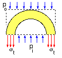
 The tangential stress is uniform across the wall; so, from equilibrium of the free body : σt = ( pi Di - po Do ) / 2 t
( 1) σt =
Δp Di / 2 t where Δp = pi - po
σa =
Δp Di / 4 t (CLOSED) or σa = 0 (OPEN)

The radial stress is zero, the tangential stress is always the principal of greatest magnitude, and the axial stress is either zero in the case of open thin cylinders or half the tangential stress in closed thin cylinders. The Mohr's circles thus appear as shown. Derivation of the design equations corresponding to the various failure theories is left as an exercise for the reader :-
| ( ii) | n Δp Di / t | = | 2 Sy | [ maximum shear stress; distortion energy (open) ] |
| = | ( 4/√3 ) Sy | [ distortion energy (closed) ] | ||
| = | 2 Sut | [ modified Mohr ] |
So much for thin cylinder theory - let us now look at the more realistic but somewhat more elaborate thick cylinder theory . . . .