A solution candidate is practical if it complies with all the problem constraints and well satisfies the problem criteria which have been identified previously. Practicalisation is the activity through which an embryo candidate solution (in all probability described only by a very hazy sketch or a few keywords) is transformed into a practical solution - if this is possible - before candidates are compared with one another and certainly before any manufacture is contemplated.
The outcome of practicalisation for a particular candidate is that :

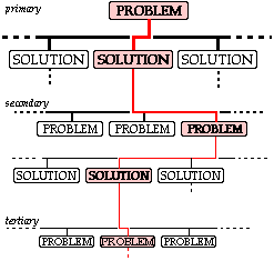
The practicalisation activity takes the form of an assessment and development of the candidate by the designer, who must modify the candidate to surmount if possible all barriers to a practical solution. The activity is seldom instantaneous but rather requires the designer to repeatedly traverse the practicalisation loop

| . . . if we adopt an existing solution then there is no problem, but if we try a novel solution then further problems are likely to arise . . . for each of which . . . . . | |
| . . . if we adopt an existing solution then there is no problem, but if we try a novel solution then further problems are likely to arise . . . for each of which . . . . . | |
| . . . . . . . . . . | |
| . . . and so on - the problems becoming smaller and smaller until they become trivial. |
One example of problems leading to other problems involves the primary problem "to design a new factory for producing a given chemical". There may be a number of different solutions to this, each with its own set of raw materials, chemical reactions, economics and so on.
If one of these solutions is adopted then the various necessary heat exchangers, pressure vessels (containers for pressurised fluids), pipes, pumps, cooling towers etc. each forms a secondary problem - some of which may be trivial as the items may be procured off-the-shelf.
The solution to one of these non-trivial secondary problems - let's say a pressure vessel - would throw up tertiary problems involving the choice of material, of dimensions, lagging to reduce heat loss, etc. etc. leading eventually into detail design.
Large problems like this require considerable resources involving large design teams for their solution. But whether the problem is large or little - if it is not known that the solution is practical before comparing it with others, then obviously the comparison is an utter waste of time as it could result in an 'optimum' which can't be made or which won't work !
Practicalisation does not equate to detail design. For example, two parts may have to be joined together demountably. Looking into the means of joining, it might be concluded that a set screw is perfectly feasible as the loads are unremarkable, access for tightening and loosening is not restricted, and so on. This is practicalisation.
Further analysis involving fatigue loading, materials and safety might lead to a solution in the form of an M10x1.5 class 10.9 socket-headed set screw, length overall 80mm, length of thread 25mm, unlubricated and torqued to 90% proof. This is detail design; it has no place in this introductory chapter on design.
During practicalisation the designer must foresee and must overcome (if possible) all drawbacks to the artefact's practical realisation. Secondary problems which the idea's novelty has introduced must be solved satisfactorily. This again is time-consuming. You have to work at it. You will have to start the problem-solving process all over again - 'How can this drawback be overcome so that this candidate can be rendered practicable ?' You will have to consider the manufacture and operation of the candidate in detail. You will need to know something about materials and how you yourself can fashion them. You may have to set up mathematical models of the device's operation, and so on.
With D&B competitions for example, the major constraints relate to the two significant life stages after design - the constraints concerned with manufacture and the constraints concerned with operation.
We shall demonstrate practicalisation first with respect to manufacture.
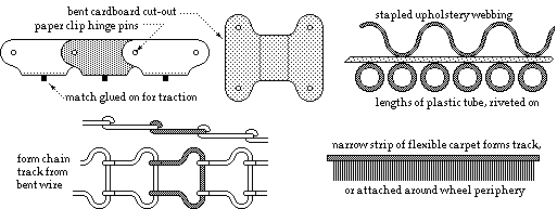
Here is another example of what can be done with even lower-tech materials and manufacture. Students were asked to design and build a stair climber. One common result of initial ideation was a vehicle equipped with caterpillar tracks like those on military tanks. The tracks were perceived as rubber belts with treads, but because nobody could conveniently lay their hands on such peculiar components the whole idea was trashed - students didn't try to practicalise . . . .

|
Both these examples are typical of D&B problems in which practicalisation is incomplete because our knowledge/experience cannot predict every detail - we don't know if we can manufacture a tube from wound fishing line or a tank track from bent cardboard. However the above ideation has indicated some possible solutions to the secondary problem of manufacture, and importantly has demonstrated that manufacture is not necessarily impossible. Note the glimmer of hope here, compared to students' knee-jerk reaction to trash both telescoping tubes and tank tracks because they couldn't immediately lay their hands on them.
Practicalisation can be completed only by acquiring the necessary knowledge, and with D&B devices this is usually best done by direct experimentation. The investment of time and effort in experimentation has been shown to be justifiable in the above examples, and would concentrate only on the unknown aspects of manufacture, not necessarily on the complete build (recall that our main aim during practicalisation is to become certain that we can or we cannot manufacture the candidate).
Let's now consider practicalising from the point of view of operation.
The principle of operation has been established during the previous ideation activity; the principle now has to be fleshed out during practicalisation - again sufficiently to satisfy ourselves that the candidate either can or cannot operate. By far the most satisfactory basis for assessing operation is direct experience of this operation. While we can't experience all aspects of operation before the artefact is completed, in most cases it is possible to quickly and cheaply experiment with certain components or sub-systems whose behaviour is particularly problematical, and to modify these to obtain the operation required. You must be prepared to try it !
This project was edifying as some competitors rejected the vacuum candidate without proper practicalisation, whereas other competitors produced successful devices based on it. Conversely, some competitors rejected conveyors on the basis of mere arguments - mere hot air with absolutely no justification, no basis in the real world. The winning device was a conveyor.
Lacking the opportunity for direct experimental appreciation of the performance of a sub-system or a device before building, it may be possible to assess operation by means of a mathematical model - though it must be emphasised that mathematical modelling is no substitute for direct experimentation if that is possible. Students generally seem reluctant to study hardware by mathematical models of their own devising - they're excellent at analysing existing models, but this ability is completely useless if no reasonably accurate model of the device exists.
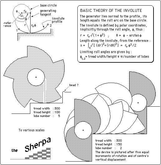
It is not suggested that mathematical modelling always be attempted - the simple party blow-up (candidate #4 of the can-raising device above) is far too complex theoretically - but rigid body dynamics eg. is often very useful in enabling prediction of operation. Students should practise the construction of such models - ensuring that free bodies are correct, a common source of error in students' work. A few illustrative mathematical models are now given.

|

|


|
Students were asked to design and build a vehicle powered by a supplied rubber band to travel as far as possible along a straight horizontal track. The rubber band, modelled as a spring, was connected to a cord wrapped around a drum attached to a large driving wheel. The spring was first wound up by rotating the wheel by hand, the vehicle was then released on the track and travelled due to the cord unwinding off the drum.
Students made the drum diameter small in an effort to achieve a large travel from a given spring displacement
 - ie. they examined only the overall geometry of motion. But the ground traction force accelerating the vehicle was proportional to the drum diameter, so a small drum resulted also in a small accelerating force. This force was so swamped by friction (which students hadn't allowed for) that there was no acceleration whatsoever. The vehicle refused to budge, causing much embarassment - or hilarity, depending on the point of view !

An even more realistic model of such a device must recognise further consequences of the choice of spring with a given energy storage - either :
Mathematical models are not restricted to mechanics, as the following demonstrates.

Assuming an adiabatic process ( n = g ), this may be solved to obtain an idea of the height H achievable - the feasibility of the device may thus be assessed.
Once a device has been built, a mathematical model can be a useful aid to understanding any unexpected behaviour which testing uncovers - eg. a vehicle will not start, or it flips over and kicks its wheels in the air, or, if propellor driven, it rotates wildly while the propellor remains stationary, and so on! Real life Research and Development entails the testing of physical models when available mathematical models lack realism. Clearly the sophistication of any modelling, whether it be mathematical or physical, must be in keeping with the importance and sophistication of the project.
Don't get carried away by mathematical or computer modelling, remember that a mathematical model is a means to an end, not an end in itself.
An extremely important task in the practicalisation exercise is to thwart Murphy by foreseeing all his worst tricks and sabotaging them. Again this requires effort on the part of the designer to visualise each life stage step by step, and to ask questions about what could go wrong with each. Thus in the case of the lobed stair climber 'What would be the effect on climber operation if the stairs were imperfect?', eg. stairs provided with an anti-slip bead, or built with a tolerance of +/- 5 mm on tread dimensions, or covered with a fluffy carpet, or copiously treated with slippery polish by the cleaner, and so on. Or again, 'If overall stability requires two identical lobed wheels on a single driving axle, what would happen if the axle became misaligned to the stair treads?'
What could go wrong with the lazy tongs, candidate #12 of the can lifter? Elastic bands would probably be used instead of the linear springs envisaged in the mathematical model;
 the bands would introduce severe non-linear and hysteritic behaviour which would render useless any quantitative deductions from the model - though qualitative findings would still be very useful.
If the tongs' struts were not 'identical' then they could bind, causing unexpected friction in the mechanism. Manufacture of the struts by drilling the three holes in each through an accurately pre-drilled jig would ensure adequate dimensional similarity.
Or, 'Murphy would try to tip over the extended can lifter - what steps would minimise overturning tendencies?' This might lead to practicalising ideas such as :
If you don't ask these sorts of questions and answer them satisfactorily then don't be surprised when (not if ) Murphy appears on the scene! So, once again . . . . YOU MUST ASK THE RIGHT QUESTIONS.
We have illustrated practicalisation by means of devices built and operated by the designers - clearly manufacture and operation are the most important life stages. But the same thoroughness and attention to detail are necessary in other aspects of more usual problems involving other folk. This is why it's so important for the designer to approach any problem from the points of view of all those likely to be affected by the solution - the lathe operator, the user, the sales person, the maintainer etc. Only by visualising the step-by-step actions of these people can the designer appreciate the subtleties of their interaction with the solution candidate.
This section concludes by emphasising the need for definite knowledge of a candidate's practicability after the practicalisation activity. Theoretically, an accurate comparison (evaluation) cannot be undertaken until all candidates have been designed completely. In choosing a new car for example, all candidates are physically available - however this is hardly a design problem, it's purely a matter of selection.
In the design context we cannot afford the luxury of designing in all detail every likely looking candidate in order to select a single 'best' solution. At the other extreme, what confidence can we have in a choice between one candidate which we don't know will work and a second which we don't know how to make? So the designer must continue around the practicalisation loop until the ultimate practicality or uselessness of each candidate is known with some certainty. Failure to do so is a one of the most common shortcomings of students' designs. All decisions must be justifiable, and they can't be if they are based on incomplete knowledge.