Involute gears have the invaluable ability of providing conjugate action when the gears' centre distance is varied either deliberately or involuntarily due to manufacturing and/or mounting errors.
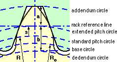
The exaggerated effect of this is shown in Fig H for gears manufactured to pressure angle α without profile shift. On the left, the gears are mounted at the standard centre distance (the sum of the two standard radii given by ( 1)) with the "cord" line of action wrapped around the base circles whose radii are given by ( 5).
On the right of Fig H the gears' centre distance is increased - but since the same generating cord is wrapped around the same base circles then it follows that the speed ratio is unaltered and the same involutes (and hence teeth) are involved. Clearly there are practical limits to centre distance variations - eg. the gears may lose contact completely - however provided these limits are not reached then the pitch point and resulting pitch circles are defined by intersection of the lines of action and of centres, exactly as occurred in Fig C above. From the similar triangles of Fig H :-
( 8 ) R'i = D'i /2 = C.zi /Σz = Roi sec α' ( i = 1,2 ) using ( 5)
There is an infinite number of possible centre distances for a given pair of profile shifted gears, however we consider only the particular case known as the extended centre distance which corresponds to mutual tangency of the two extended pitch circles mentioned above, that is :-
( 9 ) C = ( R1+ s1 ) + ( R2+ s2 ) = 1/2 Σ z + Σ s proportionally, using ( 1), or
= m ( 1/2 Σ z + Σ s ) dimensionally.
No absolute dimensions are given so it is proportions which are relevant in this example.
From ( 1) the diameters of the standard pitch circles are D1 = 12, D2 = 18. Corresponding base circle diameters are Do1 = 12 * cos20o = 11.28, Do2 = 18 * cos20o = 16.92
The pinion's extended pitch radius is R1 +s1 = 12/2 + 0.5 = 6.5 and similarly the wheel's is 18/2 + 0.4 = 9.4
The extended centre distance is thus ( 9) 6.5 +9.4 = 15.9
From ( 8) the actual pitch diameters are D'1 = 2 * 15.9 * 12/(12+18) = 12.72 and D'2 = 2 * 15.9 * 18/(12+18) = 19.08
Note that the actual pitch circles preserve the velocity ratio : 19.08/12.72 = 16.92/11.28 = 18/12 = 1.5
Also from the geometry and ( 8) the addendum diameters are Da1 = 2( 6.5 +1.0) = 15.0, Da2 = 2( 9.4 +1.0) = 20.8, while the actual pressure angle is α' = arcos( Doi /D'i ) = arcos( 16.92/19.08) = 27.5o
The meshing of typical gears at extended centres is further detailed in Figs I and J which are particularised for the 12:18 drive of the foregoing example.
Fig I shows the initial no-load situation. The gears are mounted so that the extended pitch circles (of radii 6.5 and 9.4 in the example) are mutually tangential with the pinion tooth symmetrically disposed with respect to the wheel inter-tooth space. Tangency of the extended pitch circles implies that the generating rack (shown dashed) is simultaneously tangent to the tooth profiles of both gears, and leads to a gap - an absence of contact - between the pinion tooth and both adjacent wheel teeth.
|
|
|
A pinion tooth touches a wheel tooth at the contact point C (the knot) which moves up the line of action and along the teeth faces as rotation proceeds. Since contact cannot occur outside the teeth, it takes place along the line of action only between the points Q2 and Q1 on the line of action and inside both addendum circles. The line segment Q2 Q1 is named the path of contact.
|
The animation shows clearly :
The gap between the non-drive face of the pinion tooth and the adjacent wheel tooth is known as backlash. If the rotational sense of the pinion were to reverse, then a period of unrestrained pinion motion would take place until the backlash gap closed and contact with the wheel tooth re-established impulsively. Shock in a torsionally vibrating drive is exacerbated by significant backlash, though a small amount of backlash is provided in all drives to prevent binding due to manufacturing or mounting inaccuracies and to facilitate lubrication. Backlash may be reduced by subtle alterations to tooth profile or by shortening the centre distance from the extended value, however we consider gears meshing only at the extended centre distance.
Continuous motion transfer requires two pairs of teeth in contact at the ends of the path of contact, though there is only one pair in contact in the middle of the path, as in Fig J. The average number of teeth in contact is an important parameter - if it is too low due to the use of inappropriate profile shifts or to an excessive centre distance for example, then manufacturing inaccuracies may lead to loss of kinematic continuity - that is to impact, vibration and noise. The average number of teeth in contact is also a guide to load sharing between teeth; it is termed the contact ratio, εγ, given by :-
εγ = length of path of contact / distance between teeth along the line of action
= Q2 PQ1 / base pitch, po and for extended centres with ( 6) for the 20o system :
( 10 ) ( 2π cosα ) εγ = Σ i = 1,2 √[ ( z i + 2( 1+si ))2 - ( z i cosα )2 ] - √[ ( Σ z + 2 Σ s )2 - ( Σ z cosα )2 ]
Gears having a contact ratio below about 1.2 are not normally recommended as the gears themselves, their shafts and bearings would all require especial care in design and manufacture to preserve conjugacy. The effect of tooth number on contact ratio is shown in Fig K for two identical gears with a profile shift which varies between the practical limits of Fig G. Evidently it becomes more difficult to achieve an acceptable contact ratio as tooth numbers decrease - hence the statement above that 12 teeth are the usual minimum. The plot further indicates that contact ratio increases as profile shift decreases.
In design, Σs is often taken as zero; or, if the centre distance is closely specified, by the selection of Σs for use in ( 9) - the individual profile shifts may be estimated from a specified Σs as follows :-
( 11 ) s1 = [ λ z2 + ( Σ s - λ ) z1 ] / Σ z ; s2 = Σ s - s1 ; where 0.5 ≤ λ ≤ 0.75
which tends to balance the strengths of the gears.
The procedure might take the form of a number of nested loops, each assigning a trial value to one of the design variables. For example the outermost loop would select a module from the standard list and the next would assume a trial pinion tooth number between the limits suggested above. The wheel tooth number would be assigned in the next inner loop, corresponding to the pinion teeth and a speed ratio between the specified limits.
The innermost loop would consider both profile shifts simultaneously and is best understood through a graph of s2 versus s1, realising that the module and tooth numbers have been settled in outer loops prior to this aspect being examined. The tooth numbers will define practical limits to the profile shifts ( 7), hence solutions must lie within the known rectangular region of the graph.
In addition to these limitations, there are further bounds, Σ scmin and Σ scmax, corresponding to the centre distance limits from ( 9) - these appear as the straight boundaries superimposed on the graph; and a high bound, Σ semax, corresponding to the critical contact ratio via ( 10), which appears as the curved boundary. The actual disposition of all these boundaries on the graph - which may or may not enclose a viable solution space - depends of course on the problem in hand and the values of module and tooth numbers assigned in outer loops. Having defined any such solution space, the procedure could output any solution lying within it - any point on the line between the two extreme points 'lo' and 'hi' would appear to be a suitable compromise - or alternatively ( 11) might be implemented.
Spur gears' fundamental geometry having been discussed, it is appropriate to now consider the kinetics.