half-width : h = π/4 addendum : a = 1
dedendum : b = 1.25 fillet radius : e = 0.38
- that is the tooth occupies half the pitch (π) measured along the reference line.

A tooth system is defined by a unique pressure angle and set of tooth proportions which characterise the system's basic rack of Fig D. Various systems find application in particular specialised sectors of industry, but by far the most widespread - and the only system considered here - is the 20o full depth system which incorporates a 20o pressure angle ( α) and the proportions :-
half-width : h = π/4 addendum : a = 1
dedendum : b = 1.25 fillet radius : e = 0.38
- that is the tooth occupies half the pitch (π) measured along the reference line.
A circular gear of specified module is generated by a rack cutter which takes the form of the shaded mask of Fig D. The rack's profile is a cutting edge whose straight sides and fillets machine respectively the active flanks and the roots of the gear's teeth. The cutter is set out about the reference and centre lines, with absolute dimensions derived from the system's proportions multiplied by the specified module. Cutters are available commercially to the following modules :-
m = 1 1.25 1.5 2 2.5 3 4 5 6 8 10 12 16 20 25 32 40 50 mm
Gear proportions and absolute dimensions are often used interchangeably - this should not cause confusion provided the absence or presence of units is noted carefully. Thus the dedendum of a 4 mm module gear may appear alternately as 1.25 (no units) or as 5 mm (ie. 1.25 multiplied by 4 mm). If this gear possessed 20 teeth then its pitch radius could be quoted as 40 mm ( 1) or as 10 (no units)
Generated gears ( of the same system ) which have the same number of teeth are geometrically similar to one another. One cutter only is necessary for each module, no matter how many teeth are in the gear being cut - though obviously gears become increasingly impractical as their tooth numbers fall ( imagine trying to achieve conjugacy when a gear with two teeth engages a gear having three teeth: try sketching this ! ).
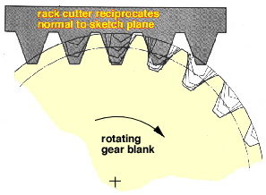
Once the cutter has been prepared, generation commences by aligning the rack's reference line with the pitch circle of the gear blank about to be cut - Fig E illustrates this for unit module.
|
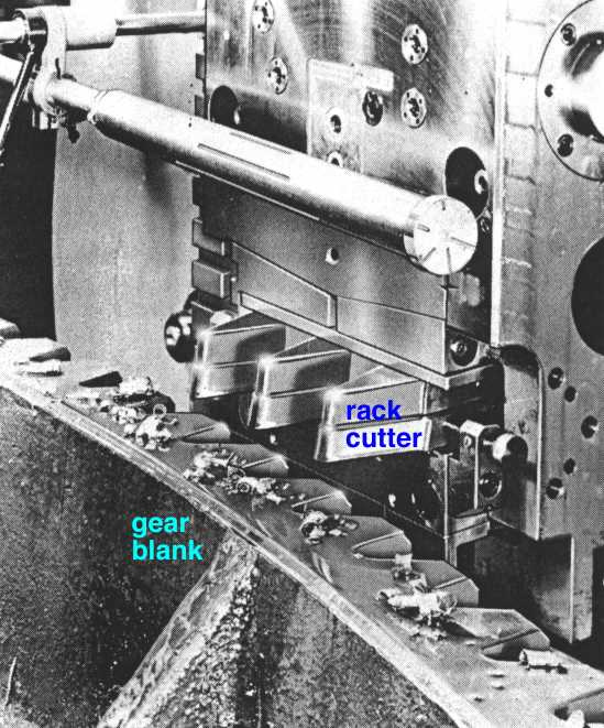
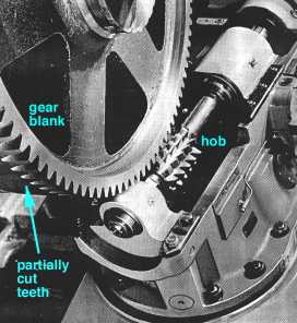
| - | it reciprocates perpendicularly to the sketch plane, Fig E, shaving material off the blank as shown in the photograph of a partially cut gear at left below, and |
| - | it translates parallel to its reference line while the circular gear blank rotates (at center below), an external mechanism being provided so that there is no slip between these feed movements. |
| 
| 
|
Before cutting commences, the rack may be displaced transverse to its reference line by an amount s ( or m * s dimensionally ) where s is the so-called profile shift coefficient ( also known as the addendum modification coefficient ), Fig F, which is introduced to lower the practical tooth number limitation. Profile shift is reckoned positive if the rack is moved away from the blank as shown above; negative if the cutter is moved towards the gear blank.
A gear's pitch circle represents the notional cylinder which rolls without slip on the pitch circle of its mating gear. The introduction of profile shift makes it necessary to distinguish between three different pitch circles :-
| - | The standard pitch circle ( Fig E ) is defined by the gear's tooth number only, thus from ( 1) this circle's proportional radius is R = z/2, or in dimensional terms R = m.z/2. |
| - | When profile shift s is present then the pitch circle is referred to as the extended pitch circle; its radius is R + s proportionally as may be seen from Fig F. |
| - | The (actual) pitch circles, R'1 and R'2 , at which two involute gears operate depend on the distance between their centres, as will be explained in the gear meshing section below. |
The following animation simulates generation of one tooth of a 10-tooth, 0.2 profile shift gear, and duplicates the relative motion of the cutting rack with respect to the gear blank whilst holding the blank stationary to better illustrate formation of the tooth flank and fillet.
 The animation shows how the cutter shaves a portion of the tooth during each reciprocation, only a few of which are illustrated.
The base, standard pitch, addendum and dedendum circles are dashed, and the rack reference origin is highlighted. The diameter of the cylindrical gear blank before cutting would exceed the addendum diameter. The useful involute flank of a tooth exists only outside the base circle ( recall the generating string ) however the flank of the illustrated tooth is interrupted just outside the base circle by the large trochoidal fillet - the tooth is severely undercut and would not be practical in a power transmission application.
The tooth form for any combination of tooth number and profile shift is simulated likewise by the Macintosh program "Gear Tooth Generator", which caters also for tooth systems other than the 20o full depth.
The potential advantage to be gained by using profile shift is exemplified below by the program's output for three 20o full depth 9-tooth gears which are identical apart from being generated with different profile shifts. Since the gears have the same number of teeth they share the same standard pitch and base circles.
|
 of highest bending stress.
For a particular number of teeth there is a critical lower profile shift below which the teeth become undercut, and a critical upper profile shift above which the teeth tips become pointed. It is unnecessary to
 consider tooth geometry further here - full details of the involute flank and the trochoidal fillet are given in Appendix B. Fig G illustrates the profile shift limits for the 20o full depth system revealed by that theory, together with the usual practical limits suggested by ISO TR 4467, namely :-
( 7 ) max [ -0.5, (30-z)/40 ] ≤ s ≤ 0.6
Desirable compactness necessitates the smallest tooth numbers possible, but these tooth form limits become more constraining as numbers decrease - eg. 20 is the minimum which theoretically avoids undercutting in the absence of profile shift. Depending upon the drive as a whole, spur gear tooth numbers of 12 are possible with suitable profile shift. Despite the indications of Fig G, numbers less than 12 are seldom used - except for lightly-loaded essentially kinematic applications - due to other considerations such as the weakness of non-pointed but thin tooth tips and the need for two pairs of teeth to be in contact simultaneously as the drive is transferred from one pair to the next, manufacturing and/or mounting inaccuracies notwithstanding (refer to contact ratio below).
The specialised business of gear manufacture and inspection is complex. The following example gives some insight into the necessity for the involute geometry of Appendix B. Not infrequently the standardised 20o full depth system is altered subtlely to improve operation.
EXAMPLE
Show that a spur gear is a body of constant width when measured as shown across tooth flanks, the difference between two such measurements giving the module of the gear.
With what standard module rack would this gear have been generated?
If there are 13 teeth on the gear, what is the profile shift ?
The measurement C1 C2 is normal to the teeth flanks and so coincides with the tangent to the base circle at T. In a similar manner, the measurement C'1 C'2 coincides with the tangent at T'.
But the arc length TT' must equal the differences in generating cord lengths TC1 - T'C'1 etc. so the measurements are equal.
Radii are drawn to the starts of the flank involutes on the base circle; these radii are inclined at γ to the tooth centre line, and corresponding radii on adjacent teeth subtend 2π/z at the centre, O. Equality of the generating cord and arc lengths requires that the measurement across n teeth is Ln = Ro ( 2γ + ( n - 1) 2π/z ), so that the difference in measurements between n and n+1 teeth is evidently Doπ/z, or, using ( 1, 5), π m cos α. Assuming a 20o pressure angle here, then m = (62.14 - 38.52)/π cos 20o = 8 mm.
A 13-tooth gear therefore has a pitch diameter of D = mz = 104 mm and from the Ln equation above :-
γ = L2/ D cos α - π/z = 38.52/104 cos 20o - π/13 = 0.1525 rad
We now need to evaluate γ as a function of s.
Figures D and F indicate that the rack space half-width on the gear rolling (pitch) circle is ( h + s tan α ), and this must equal the arc subtended by the gear half-tooth around the pitch circle, ie. rθ, where r and θ are given by ( 4 ) at r = R. From this we have :-
γ = ( h + s tan α ) / R + tan α - α or, inserting known values
0.1525 = ( π/4 + s tan 20o ) 8 / 52 + tan 20o - π/9 whence s = 0.30
One of the major advantages of involute gears is their ability to work successfully when the distance between the centres of meshing gears is altered. It's now time to consider gear meshing.