 the shape of teeth necessary for the speed ratio to remain constant during an increment of rotation; this behaviour of the contacting surfaces (ie. the teeth flanks) is known as conjugate action.
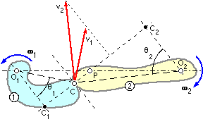
Consider the two rigid bodies 1 and 2 which rotate about fixed centres, O, with angular velocities ω. The bodies touch at the contact point, C, through which the common tangent and normal are drawn.
The absolute velocity v of the contact point reckoned as a point on either body, is perpendicular to the radius from that body's centre O to the contact point. For the bodies to remain in contact, there must be no component of relative motion along the common normal, so that from the velocity triangles :-
v2 cosθ2 = v1 cosθ1 where v1 = ω1 . O1C ; v2 = ω2 . O2C
Note that the tangential components of velocity are generally different, so sliding must occur.
For the speed ratio to be constant therefore, from the above and similar triangles :-
( 3 ) ω2 /ω1 = v2 . O1C/v1 . O2C = O1C.cosθ1 /O2C.cosθ2
= O1 C1 /O2 C2 = O1 P / O2 P ie. this ratio also must be constant.
This indicates that, since the centres are fixed, the point P is fixed too.
In general therefore, whatever the shapes of the bodies, the contact point C will move along some locus as rotation proceeds; but if the action is to be conjugate then the body geometry must be such that the common normal at the contact point passes always through one unique point lying on the line of centres - this point is the pitch point referred to above, and the pitch circles' radii are O1 P and O2 P.
There exists a host of shapes which ensure conjugacy - indeed it is possible, within certain restrictions, to arbitrarily choose the shape of one body then determine the shape of the second necessary for conjugacy. But by far the most common gear geometry which satisfies conjugacy is based on the involute, in which case both gears are similar in form, and the contact point's locus is a simple straight line - the line of action.
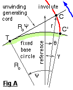
One method of generating an involute is shown in Fig A. A generating cord, in which there is a knot C, is wrapped around a fixed cylinder - the base cylinder (idiomatically circle ) of radius Ro.
( 4 ) r = Ro √ ( 1 + ψ2 ) ; θ = γ - ψ + arctan ψ
In order to see how the involute leads to gear teeth and conjugate action, we place a slightly different interpretation on the above model.
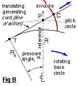
The cord is wrapped around the base cylinder which in Fig B is now free to rotate about its centre as the cord is pulled off in a fixed direction. This fixed cord direction forms the line of action, tangent to the base cylinder at the fixed point T, and clearly satisfies conjugacy by cutting the fixed reference at the fixed pitch point P through which the pitch cylinder passes. The line of action is inclined to the pitch point tangent at the pressure angle, α. The knot C always moves along the line of action, tracing out an involute with respect to the rotating cylinder. The relation between the base and pitch circle radii is evidently :-
( 5 ) Ro = R cos α
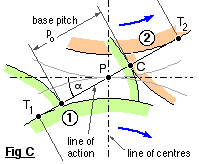
Extending this to two cylinders - representing meshing gears, 1 & 2 Fig C - the taut cord winds off one base cylinder and onto the other to form the line of action inclined at the pressure angle α. The knot, C, on the mating involutes coincides with the contact point and moves along the line of action as the gears and base cylinders rotate. The pitch cylinders extend to the pitch point P situated at the intersection of the lines of action and of centres.
Evidently the distance between the cylinders does not affect the speed ratio since the base cylinder diameters are fixed.
The distance between knots - ie. between tooth flanks along the line of action, Fig C - is the base pitch, po, given by :-
( 6 ) po = π Do / z = p cos α = π m cos α . . . . . from ( 1 )
For continuous motion transfer, at least two pairs of teeth must be in contact as one of the pairs comes into or leaves mesh. The teeth in Fig C are truncated in practice to permit rotation.
Involute generation by knotted cord is all very well conceptually, but hardly practicable as a basis for manufacturing. Only one of the many methods of gear manufacture is considered here - the rack generation technique is fundamental to the understanding of gear behaviour.