Gears are used to transmit power between shafts rotating usually at different speeds. Some of the many types of gears are illustrated below.
|
|
|
|
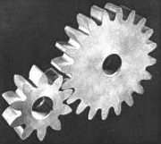
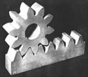
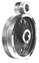
| A pair of spur gears for mounting on parallel shafts. The 10 teeth of the smaller pinion and the 20 teeth of the wheel lie parallel to the shaft axes | A rack and pinion. The straight rack translates rectilinearly and may be regarded as part of a wheel of infinite diameter | Like spur gears helical gears connect parallel shafts, however the teeth are not parallel to the shaft axes but lie along helices about the axes |
|
|
|
|
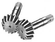
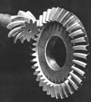
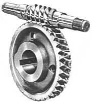
| Straight bevel gears for shafts whose axes intersect | Hypoid gears - one of a number of gear types for offset shafts | A worm and wormwheel gives a large speed ratio but with significant sliding |
In order to demonstrate briefly the development of gear drives, from first principles through to safety implications, we consider here only spur gears. Knowledge of these is fundamental to understanding the behaviour of geometrically more complex types, including helical gears which are generally preferred to spurs since they are more compact and smoother in operation, thus permitting higher speeds.
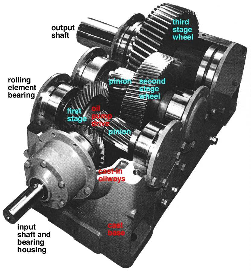
A typical commercial gearbox is shown with its cover removed. It demonstrates that it is usually more attractive economically to split a larger speed ratio into a number of stages (pairs of gears) rather than to effect it with a single pair. There are three stages here - the first spiral bevel pair is followed by two helical pairs.
A couple of features of the box are immediately apparent :
Click here for more photographs.
A pair of meshing gears is a power transformer, a coupler or interface which marries the speed and torque characteristics of a power source and a power sink (load). A single pair may be inadequate for certain sources and loads,
 in which case more complex combinations such as the above gearbox, known as gear trains, are necessary. In the vast majority of applications such a device acts as a speed reducer in which the power source drives the device through the high speed low torque input shaft, while power is fed from the device to the load through the low speed high torque output shaft.
Speed reducers are much more common than speed -up drives not so much because they reduce speed, but rather because they amplify torque. Thus gears are used to accelerate a car from rest, not to provide the initial low speeds (which could be accomplished by easing up on the accelerator pedal) but to increase the torque at the wheels which is necessary to accelerate the vehicle. Torque amplification is the reason for the gearbox's increasing sturdiness mentioned above.
These notes will consider the following aspects of spur gearing :-
Analysis of gears follows along familiar lines in that we consider kinetics of the overall assembly first, before examining internal details such as individual gear teeth.
The free body of a typical single stage gearbox is shown. The power source applies the torque T1 to the input shaft, driving it at speed ω1 in the sense of the torque (clockwise here). For a single pair of gears the output shaft rotates at speed ω2 in the opposite sense to the input shaft, and the torque T2 supplied by the gearbox drives the load in the sense of ω2. The reaction to this latter torque is shown on the free body of the gearbox - apparently the output torque T2 must act on the gearbox in the same sense as that of the input torque T1.
The gears appear in more detail in Fig ( i) below. O1 and O2 are the centres of the pinion and wheel respectively. We may regard the gears as equivalent pitch cylinders which roll together without slip - the requirements for preventing slip due to the positive drive provided by the meshing teeth is examined below. Unlike the addendum and dedendum cylinders, pitch cylinders cannot be measured directly; they are notional and must be inferred from other measurements.
|
One essential for correct meshing of the gears is that the size of the teeth on the pinion is the same as the size of teeth on the wheel. One measure of size is the circular pitch, p, the distance between adjacent teeth around the pitch circle ( ii); thus p = πD/z where z is the number of teeth on a gear of pitch diameter D. The SI measure of size is the module, m = p/π - which should not be confused with the SI abbreviation for metre. So the geometry of pinion 1 and wheel 2 must be such that :
D1 / z1 = D2 / z2 = p /π = m
. . . . that is the module must be common to both gears. For the rack illustrated above, both the diameter and tooth number tend to infinity, but their quotient remains the finite module.
The pitch circles contact one another at the pitch point, P Fig ( iii), which is also notional. Since the positive drive precludes slip between the pitch cylinders, the pinion's pitch line velocity, v, must be identical to the wheel's pitch line velocity :
v = ω1 R1 = ω2 R2 ; where pitch circle radius R = D/2
Separate free bodies of pinion and wheel appear in ( iv).
Ft is the tangential component of action -reaction at the pitch point due to contact between the gears. The corresponding radial component plays no part in power transfer and is therefore not shown on the bodies. Ideal gears only are considered initially, so the friction force due to sliding contact is omitted also. The free bodies show that the magnitude of the shaft reactions must be Ft, and that for equilibrium :
Ft = T1 / R1 = T2 / R2 in the absence of friction.
The preceding concepts may be combined conveniently into :-
( 1) ω1 / ω2 = T2 / T1 = D2 / D1 = z2 / z1 ; D = mz
That is, gears reduce speed and amplify torque in proportion to their teeth numbers.
In practice, rotational speed is described by N (rev/min or Hz) rather than by ω (rad/s).
The only way that the input and output shafts of a gear pair can be made to rotate in the same sense is by interposition of an odd number of intermediate gears as shown - these do not affect the speed ratio between input and output shafts. Such a gear train is called a simple train. If there is no power flow through the shaft of an intermediate gear then it is an idler gear.
A gear train comprising two or more pairs is termed compound when the wheel of one stage is mounted on the same shaft as the pinion of the next stage.
 A compound train as in the above gearbox is used when the desired speed ratio cannot be achieved economically by a single pair. Applying ( 1) to each stage in turn, the overall speed ratio for a compound train is found to be the product of the speed ratios for the individual stages.
Selecting suitable integral tooth numbers to provide a specified speed ratio can be awkward if the speed tolerance is tight and the range of available tooth numbers is limited. Until the advent of computers allowed such problems to be solved by iterative trials, techniques based on continued fractions were used. Appendix A is provided to illustrate the concepts and advantages of continued fractions and attendant Padé approximations - this is for general interest, not just for gears.
Unlike the above gearbox, the input and output shafts are coaxial in the train illustrated here; this is rather an unusual feature, but necessary in certain change speed boxes and the like.
In the next section we look at a particular gear train arrangement called an epicyclic gear train, before focusing on details of gear tooth shape and manufacture.