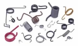
SPRINGS
Springs are unlike other machine/structure components in that they undergo significant deformation when loaded - their compliance enables them to store readily recoverable mechanical energy. In a vehicle suspension, when the wheel meets an obstacle, the springing allows movement of the wheel over the obstacle and thereafter returns the wheel to its normal position. Another common duty is in cam follower return - rather than complicate the cam to provide positive drive in both directions, positive drive is provided in one sense only, and the spring is used to return the follower to its original position. Springs are common also in force- displacement transducers, eg. in weighing scales, where an easily discerned displacement is a measure of a change in force.
The simplest spring is the tension bar. This is an efficient energy store since all its elements are stressed identically, but its deformation is small if it is made of metal. Bicycle wheel spokes are the only common applications which come to mind.
Beams form the essence of many springs.
 The deflection δ of the load F on the end of a cantilever can be appreciable - it depends upon the cantilever's geometry and elastic modulus, as predicted by elementary beam theory. Unlike the constant cross- section beam, the leaf spring shown on the right is stressed almost constantly along its length because the linear increase of bending moment from either simple support is matched by the beam's widening - not by its deepening, as longitudinal shear cannot be transmitted between the leaves.
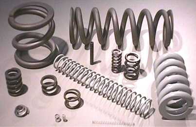
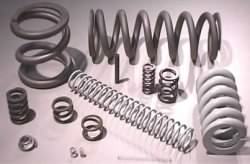 The shortcoming of most metal springs is that they rely on either bending or torsion to obtain significant deformations; the stress therefore varies throughout the material so that the material does not all contribute uniformly to energy storage. The wire of a helical compression spring - such as shown on the left - is loaded mainly in torsion and is therefore usually of circular cross- section. This type of spring is the most common and we shall focus on it.
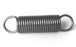 The (ex)tension spring is similar to the compression spring however it requires special ends to permit application of the load - these ends assume many forms but they are all potential sources of weakness not present in compression springs. Rigorous duties thus usually call for compression rather than tension springs.
A tension spring can be wound with initial pre-load so that it deforms only after the load reaches a certain minimum value. Springs which are loaded both in tension and in compression are rare and restricted to light duty.

A Belleville washer or 'disc spring' is a washer manufactured to a conical surface as shown by the cross- sections in this photograph. Belleville washers are characterised by short axial lengths and relatively small deformations, and are often used in stacks as illustrated. Their geometry can be engineered to produce highly non-linear characteristics which may display negative stiffness.
All the abovementioned springs are essentially translatory in that forces and linear deflections are involved. Rotary springs involve torque and angular deflection. The simplest of these is the torsion bar in which loading is pure torque; its analysis is based upon the simple torsion equation. Torsion bars are stiff compared to other forms of rotary spring, however they do have many practical applications such as in vehicle suspensions.
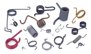
Torsion springs which are more compliant than the torsion bar include the clock- or spiral torsion spring (left) and the helical torsion spring (right). These rely on bending for their action, as a simple free body will quickly demonstrate. The helical torsion spring is similar to the helical tension spring in requiring specially formed ends to transmit the load.
The constant force spring is not unlike a self- retracting tape measure and is used where large relative displacements are required - the spring motors used in sliding door closers is one application. There exists also a large variety of non-metallic springs often applied to shock absorption and based on rubber blocks loaded in shear. Springs utilising gas compressibility also find some use.
Close-coiled round wire helical compression springs
 The close-coiled round wire helical compression spring is the type of spring most frequently encountered, and it alone is examined below. It is made from wire of diameter d wound into a helix of mean diameter D, helix angle α, pitch p, and total number of turns nt. This last is the number of wire coils prior to end treatment (see Table 1 below) - in the spring illustrated nt ≈ 8 1/2.
Close-coiled requires a small helix angle, say α ≤ 12o, where tanα = p/π D from the developed helix.
Various wire diameters are obtainable, but the availability of new springs is enhanced by specifying wire diameters from the R20 series of AS 2338 whose most frequently used decade is
. . . 0.8 0.9 1.0 1.12 1.25 1.4 1.6 1.8 2 2.24 2.5 2.8 3.15 3.55 4 4.5 5 5.6 6.3 7.1 8 9 10 11.2 12.5 . . . mm

The ratio of mean coil diameter to wire diameter is known as the spring index, C = D/d. Portions of two springs which have the same mean coil diameter but different wire diameters and hence different indices are compared here. It is clear that low indices result in difficulty with spring manufacture and in stress concentrations induced by curvature. Springs in the range 5 ≤ C ≤ 10 are prefered, while indices less than 3 are generally impracticable.
Loads are transferred into a spring by means of platens, which are usually just flat surfaces bearing on the spring ends. Various end treatments are shown in Table 1.
 Plain ends - when the wire is just cropped off to length - are suitable only for large index, light duty applications unless shaped platens or coil guides are employed, because each spring end contacts its platen at a point offset from the spring axis and this leads to bending of the spring and uncertain performance.
Ground ends distribute the load into the spring more uniformly than do plain ends, but the contact region on a flat platen will be very much less than 360o which is ideal for concentricity of bearing surface and spring axis. One or more turns at the end of a spring may be wound with zero pitch, this is called a squared or closed end. Subsequent grinding produces a seating best suited for uniform load transfer, and so squared and ground ends are invariably specified when the duty is appreciable. Grinding the ends becomes difficult when the spring index exceeds 10, and is obviously inappropriate for small wire sizes - say under 0.5 mm.
The active turns na are the coils which actually deform when the spring is loaded, as opposed to inactive turns at each end which are in contact with the platen and therefore do not deform though they may move bodily with the platen (see the animation below). The free length Lo of a compression spring is the spring's maximum length when lying freely prior to assembly into its operating position and hence prior to loading. The solid length Ls of a compression spring is its minimum length when the load is sufficiently large to close all the gaps between the coils.
Table 1 indicates how na, Lo and Ls depend upon wire diameter, total turns, pitch and end treatment, however the Table's predictions should be viewed with caution - especially if there are less than seven turns - because of variability in the squaring and/or grinding operations.
The springs illustrated here are right handed, but left hand lays are just as common. The lay usually has no bearing on performance, except when springs are nested inside one another in which case the two lays must differ to avoid interference. Springs with closed ends do not become entangled when jumbled in a container, which is sometimes an important consideration in assembly.
The spring characteristic
The performance of a spring is characterised by the relationship between the loads ( F) applied to it and the deflections ( δ) which result, deflections of a compression spring being reckoned from the unloaded free length as shown in the animation.
The F-δ characteristic is approximately linear provided the spring is close- coiled and the material elastic. The slope of the characteristic is known as the stiffness of the spring k = F/δ ( aka. spring 'constant', or 'rate', or 'scale' or 'gradient') and is determined by the spring geometry and modulus of rigidity as will be shown. The yield limit is usually arranged to exceed the solidity limit as illustrated, so that there is no possibility of yield and consequent non-linear behaviour even if the spring is solidified whilst assembling prior to operation. Sometimes a spring is deliberately yielded or pre-set during manufacture as will be explained later.
The animation illustrates the spring working between a minimum operational state ( Flo, δlo) and a maximum operational state ( Fhi, δhi) { nomenclature explanation}. If the total number of cycles is small - say less than 104 - then loading may be treated as static, otherwise fatigue considerations apply.
The largest working length of the spring should be appreciably less than the free length to avoid all possibility of contact being lost between spring and platen, with consequent shock when contact is re-established. In high frequency applications this may be satisfied by the design constraint Fhi/Flo ≤ 3.
As the spring approaches solidity, small pitch differences between coils will lead to progressive coil- to- coil contact rather than to sudden contact between all coils simultaneously. Any contact leads to impact and surface deterioration, and to an increase in stiffness. To avoid this, the working length of the spring should exceed the solid length by a clash allowance of at least 10% of the maximum working deflection - that is δs - δhi ≥ 0.1δhi, though this allowance might need to be increased in the presence of high speeds and/or inertias.
Stresses and stiffness
The free body ( a) of the lower end of a spring whose mean diameter is D :
- embraces the known upward load F applied externally and axially to the end coil of the spring, and
- cuts the wire transversely at a location which is remote from the irregularities associated with the end coil and where the stress resultant consists of an equilibrating force F and an equilibrating rotational moment FD/2.
The wire axis is inclined at the helix angle α at the free body boundary in the side view ( b) (Note that this is first angle projection). An enlarged view of the wire cut conceptually at this boundary ( c) shows the force and moment triangles from which it is evident that the stress resultant on this cross-section comprises four components - a shear force (F cosα), a compressive force (F sinα), a torque (1/2FD cosα) and a bending moment (1/2FD sinα).
Assuming the helix inclination α to be small for close- coiled springs approaching solidity ( when working loads are critical ) then sinα ≈ 0, cosα ≈ 1, and the significant loading reduces to torsion plus direct shear. The maximum shear stress at the inside of the coil will be the sum of these two component shears :
τ = τtorsion + τdirect = Tr/J + F/A
= (FD/2) (d/2)/(πd4/32) + F/(πd2/4) = (1 + 0.5d/D) 8 FD/πd3
( 1) τ = K 8FC /πd2
in which the stress factor, K assumes one of three values, either . . .
- K = 1 when torsional stresses only are significant - ie. the spring behaves essentially as a torsion bar, or
- K = Ks ≡ 1 + 0.5/C which accounts approximately for the relatively small direct shear component noted above, and is used in static applications where the effects of stress concentration can be neglected, or
- K = Kh ≈ ( C + 0.6)/( C - 0.67) which accounts for direct shear and also the effect of curvature- induced stress concentration on the inside of the coil (similar to that in curved beams). Kh should be used in fatigue applications; it is an approximation for the Henrici factor which follows from a more complex elastic analysis as reported in Wahl op cit. It is often approximated by the Wahl factor Kw = ( 4C - 1)/( 4C - 4) + 0.615/C.
The factors increase with decreasing index as shown here :-
The deflection δ of the load F follows from Castigliano's theorem. Neglecting small direct shear effects in the presence of torsion :
δ = ∂U/∂F = ∂/∂F [ ∫length (T2/2GJ) ds ] where T = FD/2
= ∫length (T/GJ) (∂T/∂F) ds = (T/GJ) (D/2)*(wire length)
= (FD/2GJ) (D/2) naπD which leads to
( 2) k = F/δ = Gd / 8naC3 in which na is the number of active coils (Table 1).
Despite many simplifying assumptions, equation ( 2) tallies well with experiment provided that the correct value of rigidity modulus is incorporated, eg. G = 79 GPa for cold drawn carbon steel.
Standard tolerance on wire diameters less than 0.8mm is 0.01mm, so the error of theoretical predictions for springs with small wires can be large due to the high exponents which appear in the equations. It must be appreciated also that flexible components such as springs cannot be manufactured to the tight tolerances normally associated with rigid components. The spring designer must allow for these peculiarities. Variations in length and number of active turns can be expected, so critical springs are often specified with a tolerance on stiffness rather than on coil diameter. The reader is referred to BS 1726 or AE-11 for practical advice on tolerances.
Buckling
Compression springs are no different from other members subject to compression in that they will buckle if the deflection (ie. the load) exceeds some critical value δcrit which depends upon the slenderness ratio Lo/D rather like Euler buckling of columns, thus :
( 3a) c1 δcrit /Lo = 1 - √[ 1 - ( c2 D/ λLo )2 ] in which the constants are defined as
c1 = ( 1 + 2ν/( 1 + ν = 1.23 for steel ; c2 = π √[ ( 1 + 2ν/( 2 + ν ] = 2.62 for steel
The end support parameter λ reflects the method of support. If both ends are guided axially but are free to rotate (like a hinged column) then λ = 1. If both ends are guided and prevented from rotating then λ = 0.5. Other cases are covered in the literature. The plot of the critical deflection is very similar to that for Euler columns.
A rearrangement of ( 3a) suitable for evaluating the critical free length for a given deflection is :
( 3b) Lo.crit = [ 1 + ( c2D/c1λδ )2 ] c1δ /2
Static analysis of a typical compression spring is illustrated by this example.
 Copyright 1999-2005 Douglas Wright,
doug@mech.uwa.edu.au
Copyright 1999-2005 Douglas Wright,
doug@mech.uwa.edu.au
last updated August 2005
 The shortcoming of most metal springs is that they rely on either bending or torsion to obtain significant deformations; the stress therefore varies throughout the material so that the material does not all contribute uniformly to energy storage. The wire of a helical compression spring - such as shown on the left - is loaded mainly in torsion and is therefore usually of circular cross- section. This type of spring is the most common and we shall focus on it.
 The (ex)tension spring is similar to the compression spring however it requires special ends to permit application of the load - these ends assume many forms but they are all potential sources of weakness not present in compression springs. Rigorous duties thus usually call for compression rather than tension springs.