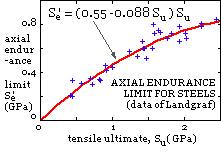
 plotted here - the fluctuating tension varying between zero and the maximum plotted. The endurance limit in threads Se is little affected by surface finish or size, so, employing Kf as a fatigue strength reduction factor, Se = S'e /Kf.
The external load on a joint assembly may vary over many cycles during the joint's life - the cylinder head joint of an i.c. engine is a typical case. The bolts of such an assembly undergo fluctuating tension and so may fail in fatigue.
| TABLE 6. Stress concentration factor, Kf | |||
| material class | rolled | cut | |
| 5.8 and below | 2.2 | 2.8 | |
| 8.8 and above | 3.0 | 3.8 | |
The traditional Goodman analysis may be employed to assess bolt safety in a particular joint assembly. Failure is most likely in the exposed threads close to the nut face where a stress concentration factor Kf models the damaging effect of the thread root notch. A rolled thread is less prone than a cut thread to fatigue damage, due to better grain orientation and surface work hardening conferred by manufacture. Representative values of Kf are given in Table 6.
Shigley op cit reports the correlation between steels' tensile endurance limits S'e and tensile ultimates
 plotted here - the fluctuating tension varying between zero and the maximum plotted. The endurance limit in threads Se is little affected by surface finish or size, so, employing Kf as a fatigue strength reduction factor, Se = S'e /Kf.
In a typical joint assembly, the initial load is Fi and the external load varies between zero and P as shown in figure ( xi) above. The bolt load therefore varies between a minimum of Fi and a maximum of ( Fi + CP ) where the joint factor C subscribes either to the stiffness ratio in ( 3a), if the stiffnesses are known accurately, or to Table 5. The corresponding alternating and mean stress components are therefore :
( 5) σa = C P / 2 As ; σm = σi + σa ; where σi = Fi / As ,
noting that σa is proportional to the external load P, and σi reflects the initial load Fi.

A Goodman analysis is thereafter straightforward; the stress components ( 5) appearing on the load line emanating at 45o from the initial stress on the mean stress axis. { nomenclature explanation}
The 'load' upon which the safety factor is based may be interpreted in one of two ways, either
- the load may refer to the load on the bolt itself, Fb, the Goodman diagram ( i) then gives
( 6a) n σi / Su + n σa ( 1/Su + 1/Se ) = 1 or
- the load may be the external load on the assembly, P, the Goodman diagram ( ii) yielding
( 6b) σi / Su + n σa ( 1/Su + 1/Se ) = 1
It can be seen that the essential difference between these interpretations lies in the inclusion or exclusion of the initial load into safety considerations. Although the second interpretation is perhaps the more correct, the imprecision with which the initial load is known may call for the conservatism of the first interpretation. A reliability or fatigue life analysis is really preferable to this traditional safety factor approach.
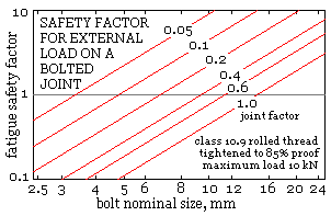
The importance in design of assessing the joint factor as accurately as possible is brought out by the plot below which corresponds to a particular joint with a single bolt.
 For this bolt material, initial tightening, and magnitude of external load fluctuation, the fatigue safety factor is given by ( 6b) as : nC = As (mm)/127. It is apparent that for a given bolt size, the safety factor is inversely proportional to the joint factor.
Thus for an M8x1.25 bolt here, if the joint factor is assessed for design purposes as 0.1, then the design would be reckoned perfectly acceptable with a safety factor of 3. But if, due to some overlooked detail, the joint factor is in fact 0.3, then there is no margin for error as the safety factor would only be 1. The implications of a poorly assessed joint factor on aspects other than bolt fatigue - eg. leakage - must also be borne in mind.
So far we have looked at groups of threaded fasteners in which the fasteners' loads are tensile and approximately the same.
 We now consider briefly joints in which the loads on individual fasteners differ and in which shear and friction can be significant.
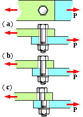
Shown at ( a) is a single bolted lap joint in which the bolt is more or less centrally located in the clearance holes in the two components. Provided it is not too large, the external load P is transmitted by friction due to pressure between the components, caused in turn by the bolt's initial tightening load. If P is such as to cause the components to slip then the components bear against the bolt shank ( b). Further increase of the external load could lead to shear failure across the bolt shank ( c), however failure in other modes might have occurred before P reached this level - failure analysis is similar to that of the cotter joint examined in an earlier chapter. It should be noted that the bolt's shear plane ( c) should lie in the shank and not in way of the exposed threads - bearing on an excessive length of exposed thread must be avoided too.