 A common application of bolted joints is for detachable connections which contain pressurised fluid. These may be rendered leakproof either by O-rings or by gaskets. An O-ring is an endless ring of circular cross- section, which is relatively compliant and usually elastomeric. It is lightly nipped when assembled, subsequent application of fluid pressure extrudes the ring to plug all potential leakage paths. Such joints are called self- energising as they do not rely on preload for their effectiveness.

|
Gasket materials range from cork to copper - each material best suiting a particular combination of fluid corrosiveness, pressure, temperature, leakage implications, cost, and so on. Most gaskets are non-metallic, highly compliant compared to other joint components, and non-linear. Their low stiffness means that other joint components may usually be neglected when figuring joint overall stiffness : 1/kj = 1/kgasket + Σ 1/kother large - that is the joint overall stiffness is essentially the same as the gasket stiffness, which has far-reaching implications in fatigue since it may not be possible to ensure that kb << kj as desired for low bolt load amplitude.
Soft gaskets usually extend over the whole flange ( full face ), whereas gaskets made of stiffer materials are narrow and extend out only to the bolt holes. It is assumed that multiple bolts are loaded equally, and that the gasket stress - ie. the average contact pressure between gasket and flange - is uniform over the gasket area Ag. Clearly the gasket stress must be higher than fluid pressure if leakage is to be avoided, and, for a given gasket stress, a raised face flange with a narrow gasket will require less preload and hence less flange strength than a full face gasket. So the tendency is for high pressure gaskets to be narrow.
| TABLE 3. Gasket material properties | ||||
| (from AS 1210) | thcknss | y | m | |
| gasket material | mm | MPa | - | |
| asbestos with binder | 1 | 45 | 3.5 | |
| ditto. | 1.5 | 25 | 2.75 | |
| ditto. | 3 | 11 | 2.0 | |
| vegetable fibre | 7.5 | 1.75 | ||
| spiral wound, asbestos filled | 69 | 3.0 | ||
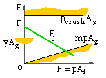
In service, the pipe acts as a closed cylinder with axial load P in the wall due to fluid pressure acting over the internal area. This loading - a preload due to initial tightening, together with an external service load - is typical of joints in general.
Codes traditionally classify gasket materials by two property values - the 'y' factor and the 'm' factor, eg. Table 3. These are necessary minimum values for the avoidance of leaks :
| y | - | the initial gasket stress ( ie. preloaded prior to pressurisation ), and | |
| m | - | the ratio of gasket stress to fluid pressure ( after pressurisation ) |

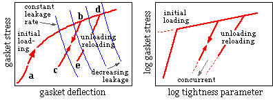
There has been a deal of debate on the suggested values of 'm' and 'y' which appear in the Pressure Vessel Codes. While the values have been found satisfactory bases for safe joint design, they are but poor indicators of leakproof operation. The Pressure Vessel Research Committee ( PVRC ) of the Welding Research Council has instituted comprehensive new tests to clarify the behaviour of gaskets, with results shown on the left below.
 Initial tightening proceeds along a-b; as the external load is applied the gasket unloads along b-c. Further cycling of the external load leads to the gasket loading/ unloading along the same b-c-b trajectory. If the bolts are further tightened then the gasket ( un )loads along the d-e-d locus.
Gaskets cannot be absolutely leak free when containing gas; locii of constant leakage rates are shown superimposed upon the characteristic. Behaviour may be described most conveniently by graphs similar to the one on the right, in which a leakage parameter replaces deflection. A material can be characterised by three constant properties - the slope and intercept of the initial loading regression line ( log-log ), together with the point through which all subsequent linear ( un )loading trajectories pass. These results have yet to be incorporated into Codes.
| TABLE 4. Gasket material stiffnesses | ||||
| width | thick | stiffness | ||
| gasket material | mm | -ness | MPa/mm | |
| compressed asbestos | 12 | 3 | 330-950 | |
| ditto. | 24 | 1.6 | 600-3260 | |
| compressed aramid fibre | ||||
| (asbestos substitute) | 12 | 1.6 | 220-490 | |
| spiral wound asbestos filled | 18 | 4.6 | 270-1800 | |
| non-asbestos laminated head gasket | 1.1 | 1140-2630 | ||
It is clear from the PVRC findings that non-metallic gaskets do not behave elastically. Table 4 gives the range of stiffnesses that may be experienced - stiffness being expressed as gasket stress ( force/Ag ) per unit deflection, ie. modulus/ thickness. Calculation of load sharing from ( 3a) is thus fraught with uncertainty if the gasket stiffness is not known accurately, however load sharing may be characterised by :
( 3b) Fb = Fi + C P ; Fj = Fi - ( 1 - C ) P
in which the joint factor C is a typical measure of the fraction of the total external load P seen by the bolts. Although comparison with ( 3a) indicates that C = ke /kj = kb /( kb + kj ) ≤ 1, the joint factor should be regarded more as an overall approximate figure of merit, which incorporates all vagaries of behaviour and which is experimentally determined in its own right, rather than as a ratio of elastic stiffnesses.
| TABLE 5. Joint factors | ||||
| type of joint | C | |||
| soft gasket held by studs | 1.00 | |||
| soft gasket with through fasteners | 0.75 | |||
| asbestos gasket | 0.60 | |||
| soft copper & long through bolts | 0.50 | |||
| metal-to-metal with long bolts | 0.00 | |||
'Flange rotation' refers to the initially disc-shaped flange assuming a flat conical form under fluid pressure loading, and can be significant when a narrow gasket is used. The cause of rotation may be appreciated from the sketches below which show rotation grossly exaggerated. At ( a) is shown part of the flange with the bolt load Fb equilibrating the external load P and the joint load Fj, as above. Accordingly Fb is split into its superimposed components ( b), which are shown separately at ( c) and ( d).

|
Operation at high temperatures leads to further difficulties with creep, ratcheting and so on.