The safety of a threaded fastener depends upon the actual load on it and the maximum load it can withstand. The latter has been considered above. Since the fastener is part of an indeterminate assembly it is now necessary to analyse such an assembly to find out just what is the actual load on the fastener itself.
The analysis is very similar to that carried out in an earlier chapter in the context of indeterminate assemblies.

|
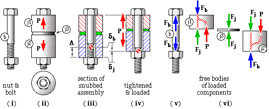
The nut and bolt b ( i) are used to connect together three joint-members j1, j2 and j3 ( ii). After tightening the nut by a known amount Δ, the external load P is applied axially to j1 and j2, and tends to separate the joint members. Joint separation must usually be avoided, so examination of the assembly has two major goals :
Evidently the bolt is under tension Fb.
Parts of the joint components j1 and j2 in contact with the nut and bolt are also subjected to the bolt load Fb, however for the case considered, the majority of these components, and all intermediate components such as j3, are subjected to the compressive load Fj only. We shall here assume that all joint components are wholly compressed by Fj - this approximation should be reviewed for other arrangements.
Solving these four equations resolves the indeterminacy, giving the component loads :
( 3a) Fb = Fi + P ke /kj where 1/ke = 1/kb + 1/kj ; Fi = ke Δ
Fj = Fi - P ke /kb
ke is the equivalent stiffness of the assembly ( ke < kb & kj ). Evidently the bolt is in series with the joint, ie. all four components are in series. Fi is the initial load ( or preload ) in the assembly due to tightening the nut by an amount Δ.

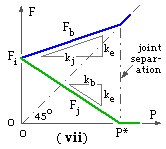
The bolt load Fb and the joint load Fj from ( 3a) are plotted in ( vii) versus the external load P, with ke < kb < kj.
When the external load is zero then Fb = Fj = Fi and the load path is a closed loop through all elements in series. As the external load increases then the joint- elements become less tightly compressed - Fj decreases - while the bolt load increases. For the case considered, the rate of bolt load increase ke /kj is less than the rate of joint load decrease ke /kb, because kb < kj.
The graph indicates that the joint force becomes zero when the external load reaches some critical value P*. Since Fj cannot be tensile ( negative by the present convention ) it follows that j3 must lose contact with the other two joint components. Thus joint separation occurs and the bolt takes all the external load, as may be confirmed by free bodies. So, after separation, Fj = 0 and Fb = P.
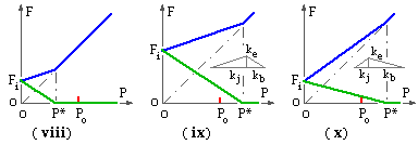
In the arrangement of ( viii) the assembly is required to sustain the external load Po without separation, but the preload and stiffnesses are such that Po exceeds the separation load P* so the requirements cannot be met - a larger separation load is necessary.

One way of increasing the separation load is to increase the preload Fi as in ( ix). The slopes of the bolt and joint load characteristics are not altered by this extra tightening. Another approach ( x) uses the same preload as ( viii) but with an increased stiffness ratio kb / kj. Clearly it is easier to alter the preload ( within the strength capabilities of the bolt and joint components ) than it is to alter stiffnesses.

In a fatigue situation with given alternating load on the assembly, P, the amplitude of the damaging fatigue load on the bolt Fb is reduced as the slope of the Fb -P characteristic is decreased ( xi). Comparing the arrangement ( ix) with ( x) it is apparent that when designing for bolt fatigue, the low-slope arrangement ( ix) is preferable - that is a relatively low bolt stiffness kb and high preload Fi are desirable.
The stiffness of an elastic component which is subjected uniformly to tension or compression is
k = F/δ = AE/L

A bolt may be reckoned as two elements in series, each with a constant cross-sectional area - the shank, and the exposed thread whose area is the stress area As. The lengths of these should include half the head and nut thicknesses respectively, to allow for local deformation. The stiffness of short bolts is less predictable than that of long bolts.
A gasket is a thin compliant sheet rather similar to j3 above, which is sandwiched between other joint components to fill up microscopic irregularities thus preventing fluid leakage. If the fastened components include a gasket, then determination of their stiffness can pose problems - we shall consider gasketed joints separately below.

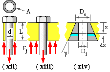
In a metal-to-metal ( non-gasketed ) joint, calculation of a fastened component's stiffness is straightforward if it is a thin tube and the external load is applied uniformly over the annular end area A as at ( xii) - but this is unusual. More commonly the component is similar to ( xiii). Known are its thickness L and the fact that there is extended reactive contact over the face which is not in contact with the bolt head or nut face. The component may be modelled as a conical frustum ( xiv) of diameter Do at the small end and cone angle γ, bored cylindrically with diameter Di to clear the bolt. The deformation dδ of a small element, thickness dx, will be :
dδ = Fj /kx = Fj ( L/EA )x = Fj dx / E π/4 [ ( Do+2x.tanγ)2 - Di2 ]
Integrating, the total compressive deformation δ over length L is found to be :
δ = ( Fj /π E Di tanγ ) ln[ ( Do - Di + 2L tanγ )( Do + Di ) / ( Do + Di + 2L tanγ )( Do - Di ) ]
It is usual to particularise this for some assumed cone angle such as 30o, but a general result has been obtained by Wileman op cit using finite elements on the basis of Di ≈ d ( small clearances ) and Do ≈ 1.5d - ie. the outer diameter of the annular bearing area under the hexagon equals the standard width across flats, Table 1. Wileman's results may be correlated for steel by :
( 4) k = Fj /δ ≈ Ed ( 0.702 +0.654 d/L ) / ( 1 - 0.12 d/L ) ; d/L ≤ 2
Use of ( 4) presumes that there is sufficient material present to allow the lines of force to develop unfettered by finite boundaries.