
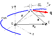
 The theory will be developed in three dimensions, and later particularised to two.
A general three-dimensional run of length L is illustrated, in which a typical element δL is located at r in a convenient centroidal Cartesian system, the centroid being such that :-
( iii) ∫L r dL = 0 ; r = [ x y z ]' see ( i) above.
The centroidal loading F & M causes the loaded member to rotate with respect to the support about a fixed centre of rotation C located at rc, so the radius s from C to the element is
( iv) s = r - rc
As a result of this rotation, compatibility requires that the strain in the joint at the element is both orthogonal to and linear in s. Presuming elastic behaviour, the stress resultant at the element - ie. the intensity q - is also orthogonal to and linear in s. This may be expressed as :
( 2) q = [ qx qy qz ]' = b x s = b x r - c using ( iv)
where b = [ bx by bz ]' is a vector constant commensurate with linearity,
the cross product ensures q, s orthogonality, and
c = b x rc = [ cx cy cz ]' is another constant vector common to all elements.
Equation ( 2) establishes the form of the intensity variation with position r along the run. It remains to evaluate the two constants b and c to define completely the dependence of q upon r. This evaluation follows from equilibrium :-
For force equilibrium, using ( 2)( 3 ) F = L c that is c = F / L - just the reversed primary intensity of the traditional method.
F = [ Fx Fy Fz ]' = - ∫L q dL = - ∫L ( b x r - c ) dL
= - b x ( ∫L r dL ) + c ∫L dL ; the first integral vanishes as a result of ( iii), leaving
For moment equilibrium, again using ( 2)
M = [ Mx My Mz ]' = - ∫L r x ( q dL) = - ∫L r x ( b x r - c ) dL
= - ∫L r x ( b x r ) dL + ( ∫L r dL ) x c ; in which the second integral vanishes, again via ( iii).
Expanding out the products in the first integral and integrating term by term (this is left as an exercise for the reader) :-

|
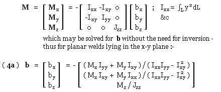
The constants b and c may thus be determined from known loading and run geometry, via ( 3) and ( 4), enabling q to be found at any point r from ( 2).
In the case of a two-dimensional joint lying wholly in the x-y plane (the only case examined at length here), z vanishes everywhere on the run, r degenerates to [ x y 0 ]', and ( 4) becomes :-
|
Resolution
The intensity q at a point in the joint run is related to the known load in global terms [ qx qy qz ]', via ( 2). Safety at that point in turn depends, via ( 1), on q expressed in terms of local components [ q1 q2 q3 ]' whose directions are dictated by the orientation of the fillet locally at the point. To avoid the need for visual inspection to carry out the global -to -local transformation - inspection which can be awkward as the above traditional example showed - we define the matrix operation :-
( 5 ) qlocal = t qglobal ie. [ q1 q2 q3 ]' = t [ qx qy qz ]'
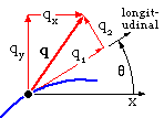
in which the 3x3 transformation matrix, t, is a pure geometric entity involving the direction cosines of the run tangent at the point in question, together with the roll angle of the fillet. We consider resolution only for the particular case of a run lying in the x-y support plane with the z- and 3-senses identical (as above).
The fillet does not roll. If θ is the inclination of the longitudinal sense (tangent to the run) in the x-y system - θ being reckoned positive anti -clockwise from the x to the longitudinal sense - then :

| 
|
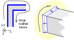
| The longitudinal sense may be remembered by the requirement for the run to be traversed clockwise when the weld plane is viewed normally, as sketched: |
Summary
The unified approach to analysing a fillet welded joint whose run consists of co-planar straight line segments involves the following steps :
The foregoing analyses rest upon rather simplistic foundations despite the apparent mathematical niceties. Three significant and questionable assumptions are the following :
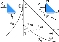 Stresses in the throat plane are assumed to be uniform over that plane. It is possible to define a more realistic stress distribution which satisfies equilibrium, compatibility and linear elastic behaviour everywhere within the fillet. The variations of the stress components on the fillet legs predicted by one such model are sketched here for q3 loading. Significant normal 'bending' stresses evidently occur in the horizontal leg, even although their force resultant is zero. The high stresses in way of the geometric singularity at the root are noteworthy. Similar stress concentration occurs with q1 loading, however such models (again) neglect compliance of the joined components - currently the effect of this can only be examined numerically, by finite elements for example.

This chapter cannot conclude without reiterating forcefully that successful welded joint design relies as much if not more on common sense and practical experience than on mathematics - no matter how appealing this last might be.