Putting it all together
We have examined individually the four steps for assessing the safety of any element of a member. These steps are fundamental and applicable to members of any form, and . . . .
. . . . in this example they are applied to a particular cross-section of a hollow circular shaft.
This problem concerned a particular hatched cross-section. But what about the other sections, and in particular the most severely loaded section? To establish the minimum safety factor for the shaft, a search must be conducted over all likely looking cross-sections, undertaking all the above steps for each. However we avoid unnecessary repetition by formulating a shaft design equation - an algebraic equation based on the above steps - which may then be applied directly and immediately to each cross-section to evaluate the safety factor.
Design Equations for (Static) Round Shafts
The foregoing steps are strung together (algebraically, rather than numerically as in the above example) to derive the design equation for a shaft's circular cross-section of outer diameter D and inner diameter ( or 'bore'), d. The equation will interrelate for the cross-section the four aspects identified previously :
- load(the stress resultant) consisting of a torque T and a bending moment M; direct stresses are presumed negligible compared to bending and torsional stresses as in the above example
- dimensions,characterised by the section modulus which by definition is Z = 2 I / D
- material,of tensile strength S ( yield or ultimate as appropriate)
- safety factor, n, at the cross-section under consideration.
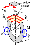
Load building blocks
The surface element lying on the z-axis is the most critical in the cross-section as it is subjected to the maximum bending tensile stress σb and also to the maximum torsional shear stress τt. The diametrically opposite element, for which the bending stress is compressive, would be equally critical if the material were ductile, but would be less critical if the material were a compressively strong brittle.
Elemental loading is plane stress, with σy = σz = 0, and, from the load building block equations :
bending : σx = σb = M ( D/2 ) / I = M / Z where Z = 2 I / D = π ( D4 - d 4 ) / 32 D
torsion : τxy = τt = T ( D/2 ) / J = T / 2 Z since J = 2 I for a circle.
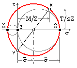
Principal stresses
Resolving in the x-y plane using ( 3a) or Mohr's circle :-
σm = M / 2 Z { nomenclature explanation}
σa = √{ ( M/2Z )2 + ( T/2Z )2 } = √( M2 + T2 )/2Z
σmax = σm + σa = + [ √( M2 + T2 ) + M ] / 2 Z > 0
σmin = σm - σa = - [ √( M2 + T2 ) - M ] / 2 Z ≤ 0
The following argument is important :
The maximum principal must be tensile; the minimum cannot be tensile; the intermediate must be zero corresponding to the z-component. The x-y circle must therefore be the largest.
Failure theories
Distortion Energy - equation ( 8) gives :-
σe =
√( σmax2 - σmaxσmin+ σmin2 ) and, since n = S/σe it follows that
( 11a) Z S = n √( M2 + 3/4 T2 )
Maximum Shear Stress - from equation ( 9) :-
σe =
σmax - σmin = √( M2 + T2 ) / Z so that
( 11b) Z S = n √( M2 + T2 )
Modified Mohr - equation ( 10) with the convenient substitution Q = √( M2 + T2 ) ≥ M becomes :-
- 2Z/n = maximum [ ( Q + M)/St, ( Q - M)/Sc, ( Q + M )/St - 2 M /Sc ]
The first term must always be the largest of the three as its numerator is larger than the second's and its denominator smaller; it is clearly larger than the third term. So :-
( 11c) Z St = n [ √( M2 + T2 ) + M ] / 2 ; the compressive strength is evidently irrelevant.
Equations ( 11) are the design equations according to whichever failure theory is being employed. Building blocks, resolution and failure theories are essential steps in any safety evaluation, but the design equations, being based on these steps, obviate the need to carry them out in detail every time a shaft is examined - provided the loading assumed in the derivation of the equations applies. The limitations of the design equations here must be clearly understood :
- Direct and contact stresses have been ignored (see above), as have stress concentrations.
 The failure theories are static theories, therefore ( 11) are strictly applicable only to stationary shafts. Power transmission shafts rotate and are subject to bending, so every element is subject to alternating tension and compression. This stress reversal is much more damaging than static stress of the same magnitude and will later be examined more thoroughly using fatigue theory. However it is permissible to employ ( 11) for the elementary design of rotating shafts, provided suitably large factors of safety/ignorance are incorporated.
It is sometimes useful to consider an equivalent bending moment Me, which, acting alone, is equivalent failure-wise to a given combination of bending and torsion. The design equations then all take the form : Z S = n Me where Me is given by the right hand sides of ( 11) appropriate to the theory in use, thus eg. : Me = √( M2 + T2 ) for the maximum shear stress theory.
The cross-section with the lowest safety factor is the most critical and defines the safety factor for the whole shaft; equations ( 11) must therefore be applied at all likely cross-sections in a search for the most critical. It is not enough to consider only the cross-section with the largest M, nor is it enough in a shaft with varying diameters to consider only the section with the largest Me.
The shaft diameters in this analysis example vary between shafts and along one shaft - a prime target for application of shaft design equations.
The following points should be noted particularly about this example :-
- The specified loading is rather uncommon; an upward reaction is usually provided at c-d.
- Once the stress resultant is evaluated at each cross-section, the design equation is applied directly, without having to consider the general steps of load building blocks, principal stresses . . . .
- The 200 Nm bending moment in the handle at d, becomes a torque of the same amount when the corner is turned, in the shaft at c. If stress resultants are difficult to appreciate, clear free body diagrams will help visualisation.
- The wrench has been designed quite well as the safety factors for the components - the shaft and the handle - are of the same order. That is, there is no link which is far- and- away weaker than the rest.
- Two significant figures in the answer are more than adequate, since the yield is given only to this accuracy, and stress concentrations in way of the diameter change at b have been neglected, as have the contact stresses in the hole for the handle, etc, etc.
Avoid excessive significant figures - they usually give a completely erroneous impression of a mathematical model's inherent approximation of reality.
Having derived the design equation for shafts, it's appropriate to now apply it to the design of power transmission shafting, noting that at this stage we're obliged to employ large design factors to account for the fact that the static theory on which ( 11) are based can only describe fatigue effects very approximately. We shall apply fatigue theory later, and derive in a manner similar to the above a more practical design equation than ( 11) specifically for rotating shafts.
 Copyright 1999-2005 Douglas Wright,
doug@mech.uwa.edu.au
Copyright 1999-2005 Douglas Wright,
doug@mech.uwa.edu.au
last updated May 2005