Approximate solutions
Codes and commercial literature employ a tabular approach to the solution of ( 5a) for the power capacity. This is based upon the following approximations for large index, m :
( iv) ( 1 + x/m )m ≅ ex ; x1/m ≅ 1 + 1/m ln x
Without going into unnecessary detail, the technique depends upon the definition of base, or reference, values of :
- life, To, corresponding to 10 years at 50 weeks/year, 6.5 days/week and 8 hours/day - that is 26 kh - and is common to all belt sizes;
- length, Lo, which is a function of belt size (refer to Table 1).
The basic rating, Po, is defined as the power capacity of a single belt of a particular size in a 1:1 drive, whose length is the reference length and whose life is the reference life. Thus, from ( 5b) :
Po = kπ v [ F ( Lo / 2 v To )1/m - M/D - ρv2 ] ; and using ( iv) :-
( v) Po ≅ v [ K1 - K2/D - K3v2 - K4 log(v) ]
in which K1 through K4 are size- dependent constants, ie. belt properties. The basic rating is thus evidently a function of belt speed and pulley diameter only - see the above graphs and the belt tables in commercial literature.
The steps in designing with typical belt tables are as follows :-
- Determine the : design power = actual power ∗ service factor where the tabulated service factor is a combination of the above duty factor, and a life factor which caters for lives other than the reference life.
- Select an appropriate belt size, guided by the carpet diagram of design power versus small pulley speed. This diagram is indicative, not prescriptive.
- Ascertain the power rating of a single belt of that size; this is a tabulated function of belt speed and small pulley diameter as noted above, the tabulation also making provision for the large pulley diameter by approximations similar to ( iv).
- The arc factor, again tabulated, caters for contact arcs other than 180o on the small pulley; it is just the ratio kθ /kπ .
- A length factor reflects the effect of a belt length other than the reference length; again the factor is tablulated.
- The number of necessary belts of that particular size follows from :
belt number ≥ design power / ( belt power rating ∗ arc factor ∗ length factor )
The tabular technique was devised before the advent of personal calculators and computers, when calculations were necessarily and laboriously carried out by slide rules. The technique is easier to use than equation ( 5a) if software such as V-belts is not available, however it gives no indication of the lives which result from the choice of a belt number different from that given by the technique. Whatever approach is employed, selection depends on costs. Belts in a drive with large pulleys may live longer than those in a drive with small pulleys, but do the savings accruing from less frequent belt replacement outweigh the cost of the larger pulleys? Is the net present worth of a few belts requiring frequent replacement greater than that of a larger number of belts which seldom need maintenance?
V-Flat and Pivoted motor drives
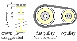
A V-flat drive incorporates an ungrooved, or flat, large pulley in the form of an existing flywheel for example, or a relatively cheap flat-belt pulley with its belt- tracking crown removed. V- belts only, and not wedge belts, can be used in this way. As the belts contact the pulley on their flat bases ( β =90o ) rather than in any grooves, the contact on the large pulley will probably limit the drive - both fθ products must be evaluated so that the minimum may be used in ( 3) et seq.
The effective pitch diameter of the larger flat pulley, D2, is greater than its outside diameter by the amount Δ (refer to Table 1).
In the typical pivoted motor drive shown at ( a) below, the base onto which the motor is bolted is free to pivot about the fixed hinge H, adjacent usually to the tight strand, thus allowing the motor's weight to tension the belt strands. Sometimes it is necessary to augment the motor's weight by a spring similar to the compression spring illustrated - however a spring is not always needed. Such an arrangement is particularly suited to short centre drives where limited belt compliance would reduce shock tolerance and part-load life if the centres were fixed - the pivot enables the belt strand tensions and bearing reactions to vary beneficially with load.
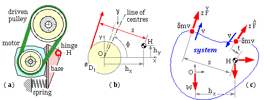
The strand tensions Fmax , Fmin in each of the z identical belts will clearly depend on the motor's weight and the layout's geometry - in order to find the tensions a Cartesian system is erected at the motor shaft axis O as shown enlarged at ( b). The hings H is defined by ( hx , hy ), and the shafts' centreline is inclined at φ to the x-axis. The moment arms about the hinge of the slack and tight side tensions are respectively :
( vi) s = hx sin( φ + γ) - hy cos( φ + γ) + D1/2 where γ is as given by ( 2a)
t = hx sin( φ - γ) - hy cos( φ - γ) - D1/2
Angular impulse/momentum theory is then applied about the hinge for the system of sketch ( c), over the small time period δτ during which identical elements of belt, mass δm, leave and enter the system with speed v. If the effective weight of motor (with spring augmentation if appropriate), pulley and base plate is W acting through the motor shaft axis, then, assuming speed and forces to be constant and taking clockwise to be positive above :
moment of impulse about H = final moment of momentum about H less initial ditto
( z Fmax t + z Fmin s - W hx ) δτ = δm v s - ( - δm v t ) where δm = z ρ v δτ
Rearranging this leads to the necessary inter-relationship between the two strand tensions of a pivoted motor drive :
( 6) ( Fmax - ρv2 ) t + ( Fmin - ρv2 ) s = W hx /z or, normalising the tensions
fmax t + fmin s = hx where fmax = ( Fmax - ρv2 ) z/W ; fmin = ( Fmin - ρv2 ) z/W
As the power transferred in a pivoted motor drive increases, the two strand tensions vary, being given by ( 4a) simultaneously with ( 6). The ratio of the two tensions also increases until it reaches the slip- limited value, given by ( 3), thus setting an upper limit to the power that can be transmitted by the drive. It is clear from ( 6) that a hinge situated close to the motor weight's line of action ( hx --> 0 ) nullifies the weight's influence, and is therefore not recommended.
Application of the foregoing analysis to a typical V-flat pivoted motor installation is exemplified here.
Traction mechanics
It has been pointed out that the classical thin belt, whose analysis led to the design equation ( 5a), models only full-load, when gross slip is imminent - it ignores adhesion as a possible mechanism for traction between belt and pulley. Some aspects of a model (Wright, bibliography) which includes both the adhesion and slip traction mechanisms, and which helps to explain the effects of initial tension and of creep will now be described. For simplicity the model is developed initially only for a flat belt in a 1:1 drive for which dynamic effects ( ρv2 ) are negligible. The belt's thickness is not negligible as was assumed in the classical theory, but is sufficient for shear deflections to be significant, thus allowing tangential friction between belt and pulley to be sustained by slip and adhesion.
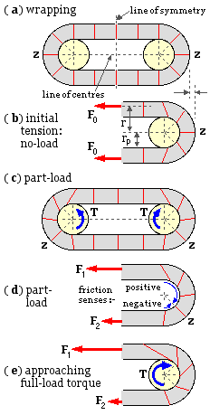
Assembly and loading of the model are illustrated. At ( a) the belt is wrapped loosely around the pulleys whose radius is rp . Edge views of belt cross-sections are shown - these are radial in way of the pulleys since the belt is taken to be wholly compliant in flexure. The pattern of cross-sections is symmetric about the line of centres and about the transverse line of symmetry lying midway between the pulleys.
At ( b) an initial tension, Fo - acting through the neutral axis of the cross-section at radius r - is induced in both strands by the pulleys being forced apart and locked in that position. The extension of the straight strands and of the belt in way of the pulleys gives rise to friction and causes shear of the belt - so cross-sections (which are assumed to remain always straight) rotate from their previous positions in ( a). By symmetry, the two cross-sections z which lie on the line of centres cannot be sheared, and therefore remain radial after initial tensioning. Symmetry also requires the sense of the friction forces to reverse across z, so there can be no friction force at z. Slip is thus impossible at z, and the belt must adhere to the pulleys at z.
Tangential friction forces arise at cross-sections other than z. Depending on the belt and pulley properties and the local surface pressure, these local friction forces may or may not reach breakaway values. If breakaway is not attained then adhesion prevails; if breakaway is reached then the belt moves locally relative to the pulley, ie. slip prevails. The tendency towards slip movement must increase the further a cross- section is removed from z on a pulley, figure ( b). The zero shear location z is thus surrounded by two adhesion zones, each of which abuts a slip zone which leads into the corresponding straight strand as shown at ( A) below. The maximum circumferential extent of each adhesion zone, θA, and the size of the slip zones, will depend upon the belt and surface characteristics, however symmetry about both the line of centres and the transverse line is maintained. If the belt is thin and relatively rigid in shear then the adhesion zones will be insignificant, however this limiting case still requires
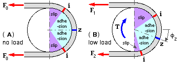
A relatively small torque load is applied to each of the pulleys in ( c), setting up unequal strand tensions F1 and F2 as shown at ( d). The pulleys are mirror images of one another, but the torque destroys any symmetry about the line of centres. The model assumes that the adhesion / slip zone system on each pulley does not change significantly under low load, apart from rotating bodily through the angle φz as shown in ( B). z now divides the total contact arc into two dissimilar regions in each of which the friction acts in a single sense, as shown at ( d). In the larger or positive region adjacent to the tight strand, friction acts on the belt in the same sense as the load torque, whereas in the negative region adjacent to the slack strand, friction on the belt is opposite to the load sense. The load is evidently transmitted by the net friction resultant. It follows that each region in general consists of an adhesion zone and a slip zone, and that the minimum tension in the belt is the tension at z, not the slack strand tension.
Upon increasing the load, the zone system rotates causing the positive slip zone to enlarge and the negative slip zone to shrink and eventually disappear when the interface i between adhesion and slip zones coincides with the slack strand tangent. Eventually the negative adhesion zone also vanishes, whereupon z coincides with the slack strand tangent, and all friction is in the positive sense contributing to torque transfer - ie. all cross-sections are rotated in the same sense as sketched in ( e). As the torque finally approaches full-load, the positive adhesion zone shrinks in turn until finally at full-load, adhesion gives way to imminent slip at the slack side contact point - gross slip is imminent and further load increase is impossible.
The relative motion of the belt over the pulley surface which the model allows is permissible, even at no- load, because gross slip is always prevented by adhesion somewhere - until full-load is reached and slip or imminent slip is universal, corresponding to the slip- limited classical theory. When the model is further developed and applied to practical belts, it is expected that they will be found to be relatively rigid in shear and the extent of the adhesion zones will be negligible. However positive and negative friction regions are still predicted, with the latter shrinking and vanishing when the load reaches its limiting value.
Development of the theory to enable evaluation of the part-load tension variation is unnecessary here - the system is statically indeterminate and must therefore be tackled using equilibrium, compatiblity and the belt constitutive laws in both tension and shear. The model has been mentioned only to give some understanding of the role of initial tension in a fixed centre drive. Clearly, once the tension variation around the pulley has been found, it is possible to integrate the resulting strains around the contact, and to find the total length of the belt. In a fixed centre drive this length remains constant as the load changes - extensions in one part of the belt due to local increase in tension must be offset by a decrease in another part.
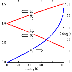
Typical results from the model are shown here; these correspond to a fixed centre drive for which the coefficient of friction is 0.5, the maximum extent of an adhesion zone θA is 60o, and the slip-limited tension ratio F1 /F2 is 4.05. The interesting aspect is the essentially linear dependence of the strand tensions with load. This approximate linearity was found for all cases studied via the model, including thin belts with friction coefficients as low as 0.1. It was found that, for the most part, the ratio of the slopes of the two tension variations fell within the bounds :
( 7 ) 0.66 ≤ ( F1 - F0 )/( F0 - F2 ) ≤ 0.80
- that is F0's increase to F1 is less than its decrease to F2 . It is noticed that this linear behaviour is similar to that of the pivoted motor drive ( 6).
Apart from giving a clearer understanding of the mechanics involved in power transmission by belting, the model enables part- and no-load tensions to be evaluated, and more economic drives chosen.
EXAMPLE
A belt which behaves according to the above model has to be selected to transmit 3 kW continuously, however it might be called upon to transmit 4 kW in an emergency. The belt speed is 20 m/s but centrifugal effects are negligible. The maximum possible friction- dictated tension ratio is 5. The speed ratio is 1:1.
-
- Assume that gross slip is imminent in peak emergency conditions, so from ( 4a) ( 3) :
F1 - F2 = 4E3/20 = 200N ; F1 /F2 = 5 - solving gives F1 = 250 N, F2 = 50 N
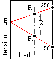
Under normal continuous conditions at 3 kW, from ( 4a) ( 7) :
F1 - F2 = 3E3/20 = 150 N ; 0.66 ≤ ( 250 - F1 )/( F2 - 50 ) ≤ 0.80
. . . . from similar triangles assuming linear load dependence :-
Solving gives mid-range values F1 = 230 N, F2 = 80 N, F0 = 165 N
The belt would be selected on the basis of these last figures and the belt's known life- load interdependence - clearly a more rational selection process than any possible using the classical thin belt theory.
The example utilised a maximum tension ratio of 5 which is characteristic of V- and wedge-belts - however it must be pointed out that the model has yet to be proved suitable for such belts.
 Copyright 1999-2005 Douglas Wright,
doug@mech.uwa.edu.au
Copyright 1999-2005 Douglas Wright,
doug@mech.uwa.edu.au
last updated May 2005