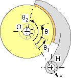
The long rigid rotational shoe is analogous to the long translational shoe examined above. In both cases the location of a point along the lining is reckoned from the hinge, however in the present cylindrical embodiment the angle θ rather than x is the obvious independent geometric variable. The lining of constant width w normal to the sketch plane extends between θ1 and θ2.
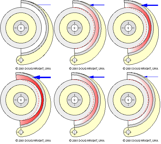
The lining illustrated below is impractical in extending from 0o to 180o with grossly exaggerated thickness and compliance to hilite the crescent- shaped distribution of lining deformation arising from changing actuation. By inspection for any given actuation the deformation is zero at θ = 0o , 180o and a maximum at 90o. Assuming the lining to behave elastically, the compressive stress and the contact pressure p also vary in this manner. A sinusoidal pressure variation is thus a reasonable postulate for practical linings which are not wholly elastic, thus

( 9) p = pmax sinθ ; θ1 ≤ θ ≤ θ2
pm = ∫12 p dθ / ( θ2 - θ1 ) = pmax Is / ( θ2 - θ1 )
in which pmax is the pressure at θ = π/2 . For a certain actuation there is a corresponding pmax and hence a corresponding pressure distribution via ( 9) - just like the lining deflection in the animation.
pm is the average pressure over the whole lining, and the integral Is together with other relevant integrals are defined as
| ( 10) | Is | = | ∫12 sinθ dθ | = | cosθ1 - cosθ2 |
| Iss | = | ∫12 sin2θ dθ | = | ( 2θ2 - 2θ1 - sin2θ2 + sin2θ1 )/4 | |
| Isc | = | ∫12 sinθ cosθ d&theta | = | ( cos2θ1 - cos2θ2 )/4 | |
| Ic | = | ∫12 cosθ dθ | = | sinθ2 - sinθ1 | |
| Icc | = | ∫12 cos2θ dθ | = | ( 2θ2 - 2θ1 + sin2θ2 - sin2θ1 )/4 |
A long shoe is analysed by dividing it up conceptually into infinitessimal elements - each of whose contact with the braked body is identical to that of the short shoe above - then summing (integrating) the equilibrating effect of all the elements. Thus the element of lining dθ at θ in the sketch below is analogous to the short lining of sketch ( c). The element's contribution to the contact resultant at the shaft centre O is
dFx = Δ.dN cosθ - δ.μ.dN sinθ ;
dFy = Δ.dN sinθ + δ.μ.dN cosθ ;
dT = μ.dN r
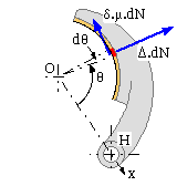
The pressure p is essentially uniform over the short element, so the normal reaction on the element is dN = p dA = pmax sinθ.wr dθ using ( 9). The x-component of the resultant contact force, sketch ( d), is therefore
Fx = pmaxwr ∫12 ( Δ cosθ - δ.μ.sinθ ) sinθ dθ
= pmaxwr [ ΔIsc - δμIss ] using (10)
Proceeding in like manner for the y-component and for the torque leads to :-

|
ΔM = a Fy - δT = No [ a ( δμ Isc + Δ Iss ) - δμ r Is ] - and solving for No
( 6b) No = M / [ μr Is ( m - δΔ n ) ] in which m ≡ 1/μ a/r Iss/Is and n ≡ 1 - a/r Isc/Is
are constant dimensionless characteristics of the shoe.
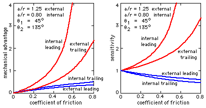 It is apparent that a short shoe is just a limiting case of a long shoe - the geometric integrals in ( 5b) and ( 6b) become simple circular functions in the short shoe equations ( 5a) and ( 6a). The general trends of mechanical advantage and sensitivity for the two cases are thus very similar, as may be seen by comparing the graphs here for typical long shoes with the corresponding graphs for short shoes.
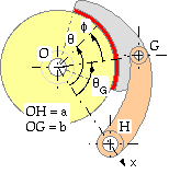
The hinged shoe is connected to the actuated post by the hinge, G, which introduces another degree of freedom - so the shoe tends to assume an optimum position in which the pressure distribution over it is less peaked than in a rigid shoe. The extra expense of providing another hinge is thus justified on the grounds of more uniform lining wear. The pressure consists of two components; one, proportional to sinθ, due to rotation of the post- and- shoe about H; the second, proportional to sinφ, due to rotation of the shoe alone about G. Since φ = θ -θG we may take the pressure variation as :-
The x-component of the contact force resultant becomes :-
Fx =
Δ ∫12 cosθ ( ps sinθ + pc cosθ ) wr dθ -
δ μ ∫12 sinθ ( ps sinθ + pc cosθ ) wr dθ
=
Δ ( Ns Isc + Nc Iss ) -
δ μ ( Ns Iss + Nc Isc ) from ( 10), and
where by definition : Ns ≡ w r ps ; Nc ≡ w r pc
The y-component and the torque may be found in a similar manner, to yield :-

|
Equation ( vi) still applies to the free body of the post-and-shoe, giving :-
( 6c) M = α ( Js Ns + Jc Nc ) where
α = [ δΔ μa a -δΔ μr ] ; Js = [ Isc Iss Is ]' ; Jc = [ Icc Isc Ic ]'
The actuating force P is applied to the post HG so the shoe itself is subject to two contacts only - the (ideal) pin at G and the distributed contact with the drum. For equilibrium of the shoe :-
Σ MG = T + Fx by - Fy bx = 0 where bx = b cosθG by = b sinθG
which, with ( 5c), requires that :-
( 11) β ( Js Ns + Jc Nc ) = 0 where β = [ ( δΔμbx - by ) ( δΔμby + bx ) ( - δΔμ r ) ]
This relation lays down the necessary inter-dependence of Ns and Nc - that is of ps and pc - for equilibrium. The forces and torques as given above are therefore all expressible in terms of a single pressure parameter, and equations ( 5c) and ( 6c) take the same form as ( 5a,b) and ( 6a,b) respectively. Thereafter the treatments of the various cases are very similar.
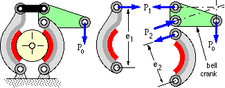
Shoe behaviour has been discussed at length. Two such shoes are combined into a complete practical brake unit, two being used to minimise the unbalanced forces on the drum, shaft and bearings, and because, as has been seen, linings become increasingly ineffective if they extend much beyond 90o to 110o. The shoes will be designated 1 and 2.
The brake torque of the complete brake To is the sum of the torque contributions of the two shoes. The shoes are operated by a single brake actuation source Po which may be a force in a brake rod or an hydraulic pressure for example. This source is converted into the individual shoe actuations by some actuating linkage, examples of which are shown at the beginning of the chapter. Since the two shoes usually behave differently - one leading while the other trails - the actuating linkage is arranged to have different transformation ratios between the source and the shoes so that the linings' peak pressures and lives are not too different. Expressing this mathematically
( 12) M1 = λ1 Po ; M2 = λ2 Po
where λ1 and λ2 are geometric actuation constants which reflect the actuation linkage's mechanical advantages. The dimensions of λ will be [length3] if Po is an hydraulic pressure, or [length] if Po is a force - thus for the linkage sketched above, λ1 = P1 e1 /Po and λ2 = P2 e2 /Po both depend upon the geometry of the bell crank. Clearly in designing such brakes, the economics and reliability of more complex mechanisms must be considered.
For geometrically similar shoes, the shoe with the largest λη product will be subjected to the greatest lining pressure and will contribute most to the total braking torque To. The contributions of the two shoes to the mechanical advantage ηo and sensitivity So of the brake as a whole may be expressed as
( 13) ηo = To /Po = Σ λη ; So = Σ ληS/ηo
which lie somewhere between the values for the individual shoes ( see tutorial problem #2 ).
If rotation is essentially unidirectional, as in a car, the two shoes may be arranged so that they are both self-actuating. Although a more elaborate actuating linkage will be required, hydraulics do make this easier to accomplish.
Despite the apparent complexity of the hinged shoe equations, proportionality is inherent between the three parameters of most interest - actuation torque, lining mean pressure, and braking torque - for all shoe types considered. The simplest way of tackling many brake problems, if not the most elegant, is therefore to assume any convenient reference actuation source value, and work out all shoe parameters on that basis using ( 12), ( 5) and ( 6). A final scaling of all values would then be carried out as shown by the following example.