
Before the widespread industrial use of electricity, the individual machines in a manufactory for example were powered by flat leather belts from a roof -mounted network of rotating shafts and pulleys, driven in turn by a centralised power source - perhaps a waterwheel or a steam engine. The whole power distribution system was mechanical. Napier & Sons engineering works shown in this photograph circa 1910 was typical in resembling a forest of belts which were inefficient, unreliable, dangerous and limited in the power which could be transferred to a single machine.
This chapter on squirrel cage electric motors, together with the following chapters dealing with V-belts, gears and brakes, concentrates on the problem of safely powering machines. The electrical theory which underpins the motors is hardly mentioned - we concentrate on the mechanical aspects.
Squirrel cage motors get their name from the appearance of early rotors. They are the most common type of industrial AC electric motor, being rugged and requiring neither a separate DC power source nor slip-rings. They are essentially constant speed devices when energised by a constant frequency AC supply, however electronic speed control is available.
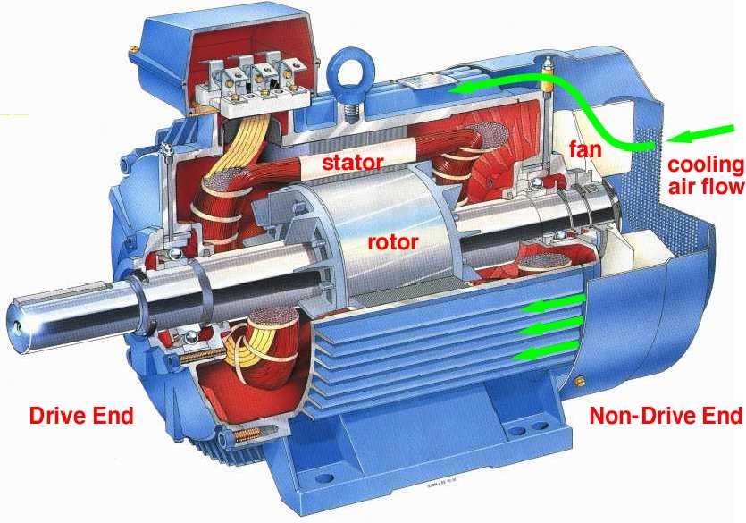
The majority of industrial squirrel cage motors are foot mounted Totally Enclosed Fan Cooled (TEFC) as shown here, in which the motor internals are isolated from the surrounding environment by shaft seals etc, thus minimising the ingress of dust and moisture. The inevitable heat generated by I2R losses in the internal windings is transferred to the surrounds by air circulation within the casing together
 with cooling air blown by an integral fan along fins on the casing's exterior.
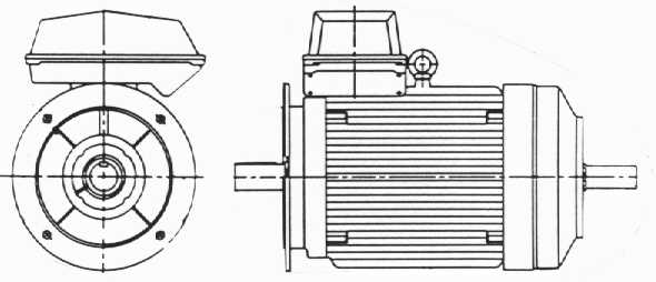
A variety of forms other than TEFC meet specialised needs - motors may be dust protected, ignition proof and so on. A flange- rather than foot- mounted motor with shaft extension is illustrated. Integral brakes or gearboxes also are available - suppliers' brochures should be consulted for full details.
Squirrel cage motors are not without their drawbacks, notably during starting when current drain is high. Mechanical aspects will be stressed here - we are interested mainly in how to select a motor to drive a given mechanical load - but it is essential to appreciate in broad terms the thermal -electrical behaviour when selecting a motor, since the winding temperature dictates the life that results, as suggested by the sketch. It is the motor's heat dissipation capability dictated by heat transfer and the integral fan which to a large extent determines the motor's maximum continuous mechanical power rating for winding temperatures commensurate with an acceptable life.
A load needs a torque T to drive it at speed nL. A load which is predominately frictional in nature requires a constant (speed-independent) torque; conversely a hydrodynamic machine such as a centrifugal fan or pump needs a torque which varies approximately as the square of the speed. Before an economic motor can be selected to drive a load, the load's steady state torque-speed characteristic should be known - this may be generalised by :
( 1a ) T = T0 + T1 ( nL /no ) + T2 ( nL /no )2 + . . . etc.
in which no is some convenient reference speed and T0 , T1 and T2 are constant properties of the load, dictated by the type and size of the load. We will neglect third and higher orders here. Most practical loads are modelled by two terms at most in ( 1a), thus a characteristic with non-zero T2 and with T0 = T1 = 0 might represent an axial flow fan's approximate behaviour.
More often than not a load is driven through a speed reducerbased on gears, or belt & pulleys, chain & sprockets or other mechanism. A speed reducer is usually provided not to reduce speed but to increase torque. A car's gears eg. are necessary to amplify engine torque and so provide high torque at the road wheels to accelerate the car or to move it uphill against gravity - if speed reduction were the only goal then it could be achieved without a speed reducer simply by easing up on the accelerator pedal.
If a load is driven through an ideal speed reducer of ratio R (≥1), then the speed of the reducer's input shaft is n = nL ∗R, while the torque on this shaft necessary to drive the load is TL = T/R since the power fed into the ideal reducer ( ∝ nTL ) must equal to the output power ( ∝ nL T ) transferred from the reducer to the load. The steady state torque -speed characteristic of the load referred to the reducer's input shaft is therefore, from ( 1a) :
( 1b ) TL = { T0 + T1 ( n/Rno ) + T2 ( n/Rno )2 } / R
The losses from practical speed reducers are normally around 5%, though gear efficiency can exceed 99% whereas the efficiency of a hydrostatic speed reduction may not reach 70%. Losses are neglected in ( 1b). The effects of cyclic load variation are examined below.
Turning now to the motor - a squirrel cage motor may be regarded simplistically as a stator winding through which AC flows thus causing an EMF to rotate at synchronous speed,ns given by ns = 2∗frequency/number of poles. The number of poles depends upon the electrical build - two, four, six or eight pole motors are available, however the most common machines are four pole, with a synchronous speed of 1500 rev/min when supplied at 50 Hz.
If this simplistic motor were ideal and there was no external drag on the rotor then the rotor would be pulled around by the EMF also at synchronous speed, however when an external brake is applied to the rotor shaft it slows down to some speed n which is less than synchronous. The proportional drop in speed is called the slip,s, given by s = ( ns - n )/ns . Clearly the greater the braking torque applied externally to the rotor (ie. the torque developed by the motor), the greater the slip and the lower the rotor speed. If there is no slip then there is no torque developed by the motor.
The complete torque -speed characteristic for a typical squirrel cage motor shown here demonstrates this increase in torque as the slip increases from zero - ie. as the motor speed decreases from synchronous. At starting the speed is zero, the slip is unity and the starting torque is Ts. The torque of a small motor may decrease monotonically from starting, without a distinct minimum or maximum.
Full load refers to the maximum continuous torque Tf that a motor can generate without overheating - a motor can operate continuously only at points on the characteristic between full load and synchronism.
The attached data for ABB motors is typical of the information published by manufacturers. Some notable features of the data include :
 The system inertia (of which the tabulated rotor inertia is a part) is relevant to starting, as may be appreciated by the variation of current in a typical motor illustrated here. The starting current is around seven times the full load current, so the I2 R losses at starting are some fifty times the full load losses - and the motor's cooling sytem can handle only the full load losses over an extended period without overheating. It is therefore necessary when selecting a motor to ensure that the time of acceleration does not exceed the manufacturer's tabulated limit - the DOL time, when the motor is connected Direct On Line (as opposed to other current -reducing starting techniques).
The determination of motor acceleration requires the complete torque -speed characteristic similar to the curve above - the discrete performance data tabulated above is not sufficient. The complete characteristic is usually available from the motor supplier on request, but lacking this the following torque -speed approximation is useful :-
( 2 ) TM = Tb / ( 1 + ( sb - s )2 ( a/s - b s2 ) ) ; s = 1 - n / ns
in which sb and Tb (the slip and torque at break-down ie. at maximum torque), a and b are all constant properties of the motor. The tabulated values have been chosen to fit ( 2) to the manufacturer's performance data together with an estimated pull-up (minimum) torque of Ts - ( Tb -Ts )/2. Elementary theory predicts b = 0.
We now consider a motor connected to a load. The load may incorporate a speed reducer, or it may not (R=1) - in either case the load characteristic is given by ( 1b). When energised, the motor torque TM must always exceed the torque absorbed by the load TL since the excess torque Tnet = TM - TL is necessary to accelerate the system of motor -plus -load until the system settles at a steady running speed nr where torque equilibrium obtains,
 ie. TM = TL = Tr , and the two characteristics ( 1b) and ( 2) intersect. It is unlikely that an accurate solution for the running speed will be necessary since Code specifications allow for a tolerance of ± 20% on the full load slip - if a precise running speed were required then a motor or control system more sophisticated than the DOL started squirrel cage would be used.
As noted previously, full load refers to the maximum torque which a motor can develop on a continuous basis, and is dictated largely by the motor's inbuilt cooling system. The running point sketched here is therefore NOT suitable for extended periods because winding temperatures would increase leading to insulation breakdown. If continuous duty is called for then Tr ≤ Tf .
Theoretically, driving a load at low speed may be carried out equally well by a directly coupled low speed motor or by a high speed motor and speed reducer. In practice the high speed motor / reducer option is very often the cheaper for a number of reasons :
 An electric motor is much more complex than a gearbox for example, and its power density (kW/m3 ) is less since it relies on EMF rather than on highly stressed metal teeth for torque generation. So it makes economic sense to develop torque in a mechanical transformer rather than in an electro -mechanical transducer such as a motor. However there is a limit to this arguement ( why are two pole machines not more common ? ) and the real costs of various solution candidates must be compared before any optimum can be selected.
 It is seldom prudent to rigidly connect together nominally coaxial power transmitting shafts - of motor and load or of anything else - since real misalignment gives rise to untoward bending stresses and vibration. Misalignment to some extent is inevitable due to tolerances in initial assembly, to load- or thermally- induced support movement, to shaft bending under load, and so on.
Misalignment is allowed for by connecting the shafts by a shaft coupling - some of the many types of coupling are shown below ( click here to see more ). Each half- coupling is connected rigidly to one of the two shafts by key, contracting friction bush, or by other means. The motor and drive assembly is then adjusted to minimise the initial misalignment (see eg. tutorial problem #9) the motor is then tightened down and the half couplings are finally connected together by a dismountable flexible element.
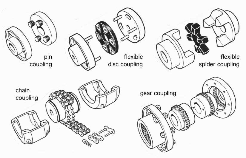
The choice of coupling depends on the speed and energy level of the connected machines, on the degree of misalignment which the coupling can tolerate, on the torsional vibration level present, and so on. Thus the flexible spider coupling might be expected to cater for greater misalignment than the gear coupling, and also to provide more damping - but the torque capacity of the gear coupling would be much greater than that of the flexible spider because the metal gear teeth are much stronger than the rubber spider.
Shaft alignment is important also when driving through belts. The plan view here shows a motor equipped with a belt pulley and mounted on slide rails which are fixed.
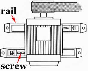 During installation the motor can slide on the rails and is positioned by the two adjusting screws so that the belt is correctly tensioned and the motor axis is perpendicular to the belt length (if it isn't perpendicular then the belt might run off the pulley). When adjustment is complete the motor is secured to the rails.
The opposing orientation of the adjusting screws should be noted.
So far we have considered only uniform loads, it's now appropriate to look at non-uniform loads.