


Some Guidance on the Design of Retractable Roofing
Roof Dimensions
The first, and perhaps most important, consideration is the size of the stadium roof: it is not necessary to design a moveable/retractable roof that covers the entire stadium. In general, existing stadiums with deployable roofs can be divided in two categories:
- The majority of the roof, the part that covers the spectators, is stationary. The retractable part, usually approximately the same size as the pitch, is therefore in the middle of the stadium. Thus the spectators protected from the elements under all conditions, hence games can happen under light rain. In very poor weather the roof is completely closed, allowing a match to occur regardless of the conditions outside. However at some times of the day the pitch may be partly in shadow due to the position of the sun and the relatively small opening in the roof. This can be distracting for both players and spectators.
- The whole roof is retractable. When conditions are good, spectators may enjoy games in the full open air, and the possibility of shadow on the pitch is reduced. On the other hand such a roof is much harder and expensive to design and implement.
As always, compromises will probably be necessary The design decisions taken must be based primarily on the available budget and the prevalent weather conditions in the country the stadium will be built. For example, how often does it rain during the football season in the UK?
Aesthetics - Materials
In recent years many stadiums have attempted to gain additional income from tourism, due in no small part to their breath-taking design. Often at the cutting edge of modern engineering and architecture, retractable roofs for stadia can be spectacular features.
Hence architects and engineers put a lot of effort in to designing a roof that will be unique, interesting, attractive, and most importantly functional. Different designers adopt different strategies using either traditional or modern materials. There is currently a trend towards the use of transparent materials, making the design more eye-catching and allowing a greater amount of light to enter the stadium.
Loading
The first key design calculation is to estimate the probable maximum loading of the rood. The main loading is the self-weight of the roof, including all the equipment fixed on the roof like lighting, ventilation fans, walkways etc. Other contributing factors to consider the loading of the roof under, for example, a heavy load of snow.
Estimate the self-weight of the roof: Make an estimate of the average thickness of the roof (t), then multiply it by its area (A) and density (r).
For example a steel roof with density r=7800kg/m3 and dimensions 50x100m (roughly equal to the size of the pitch) of average thickness t=10cm will weigh:
Wself = (7800 x 50 x 100 x 0.1) / 1000 = 3900tons
An equivalent roof made of Aluminium would weight about 1400tons.
Estimate the snow load: The density of the snow is 300Kg/m3, thus if a thin 20cm layer of snow accumulates on the roof, this will add an extra load of:
Wsnow = (300 x 0.2 x 50 x 100) / 1000 = 300tons
Which is quite significant for just 20cm of snow!
Frictional Forces: Driving power
Almost all existing retractable roofs on stadiums move using a sliding mechanism. Most mechanisms involve two "doors" that slide on rails, driven by motors. At the points of contact between the moving and stationary parts, enormous frictional forces develop due to the huge weight of the moving parts as the roof opens and closes.
As an example let as consider a door spanning half the gap i.e. 50x50m. Take its self weight plus any extra load as W = 2200tons, the coefficient of friction m=0.2 and the speed of opening/closing to be about v=2m/min.
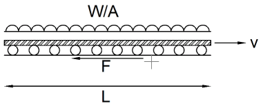
In this case the frictional force, F = mW, = 0.2x2200 = 440tons and the power needed to move this door is P = Fv = (440 x 9.81 x 2) / 60 = 144kW. (Motors must apply a force equal and opposite to F to move the doors at a steady speed). Thus, in total, if both doors move at the same time, the power requirement is almost 300kW!
Wheel forces
The total weight is carried by a number of wheels which must have a failure strength in excess of the maximum loading of the roof. So for above case (W=2200tons), if the available wheels can carry 10tons then 220 wheels are required to support the roof. The wheels transfer this load to the stationary part of the roof, which must hence also be designed to be able to carry these forces.
Thickness of the roof
In order to avoid collapse of the moving doors under maximum loading, they must have a minimum thickness.
Lets consider a design where we have two flat steel doors, each 50x60m carrying a total load Wdoor = 2500tons, L=60m and b=50m
Design 1: The wheels run along the two parallel sides of length L only and the other two sides are unsupported.
The following equation must hold:
syt2 / 4 > Wb / 8L → t2 >Wb/(2Lsy)
sy=300MPa for steel thus:
t2 > (2500 x 1000 x 9.81 x 50) / (2 x 60 x 300) → t > 185mm = 18.5cm
Design 2: The wheels run along the two parallel sides of length L and on one of the other sides of length b and the other side is unsupported.
The following equation must hold:
syt2/4 > Wb(6L-b) / 24L(2L+b) → t2 Wb(6L-b)/[6L(2L+b)sy]
sy=300MPa for steel thus:
t2 > [2500 x 1000 x 9.81 x 50 x (6x60-50)] / [6 x 60 x (2x60+50) x 300] => t > 144mm = 14.4cm
In real life, stadium roofs are not just sheets of metals but are complicated frameworks clothed with some other light, usually transparent, material.
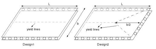
Note: The yield lines shown on the picture are the lines along which the roof panels are expected to bend and fail if the maximum load is exceeded.
Scaling parameters: from real life to the model
We need to scale everything down from the real life dimensions to the model size. To do these we use a multipicative scaling factor on all the dimensions. For example say we have a scaling factor r = 1/500. That means an opening of dimensions 50x100m will become:
50 / 500 = 0.1m = 10cm; 100/500 = 0.2m = 20cm i.e. 10x20cm.
Same thing happens with the thickness of the roof, thus for the above example, design 1 where we had thickness t = 18.5cm, on our model this thickness is just 18.5/500 = 0.037cm = 0.37 mm.
To find the load it will have to carry the calculation is a bit different. The following ratio must be the same for both real life and model: (sy L2 /gW)model = (sy L2 /gW)real . If we simplify this, and taking into account that r=Lmodel /Lreal , we obtain the following equation:
Wmodel = Wreal(symodel/syreal)r2
Thus for a the real size stadium made of steel and W=2200tons for one door, for a steel model:
Wmodel = 2200x1000x(300/300)x(1/500)2 = 8.8Kg
for an Aluminium model (sy = 200MPa)
Wmodel = 2200x1000x(200/300)x(1/500)2 = 5.9Kg