


Challenge 4: Bridge Design
Loading Specification
The bridge is required to span 840 mm clear between 300 mm wide supports and to carry a vertical load, W, at mid-span, as shown. The structure will simply rest on the support platens (simulating river banks), but provision must be made for locating it correctly. No horizontal force may be taken by the supports – i.e. the bridge must rest across the gap but must not push against the vertical faces of the banks.
At one end the 300 mm wide support is only 75 mm deep. At the other end the support is of unlimited (within reason) depth.
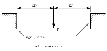
At the loading point, the structure must have a plate in a vertical plane with a 13 mm diameter hole to receive the loading gear. This plate may occupy any vertical plane, but the centre of the hole must lie 50 mm vertically below the level of the supports. The plate thickness must be adequate to resist tearing out.
The working load is W = 3500 N; at this load, there must be no visible deformation.
The objective is to design a structure with the given material that will satisfy the loading conditions.
If you opt for a design using cables (e.g. a suspension bridge), it is possible to anchor cables at one or both supports. Consult your team mentor about the details of how to do this, if you are interested in this possibility.