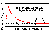

Specimens of a given ductile, having standard proportions but different absolute size ( characterised by thickness ) give rise to different measured fracture toughnesses, as indicated here.
| material | yield | toughness | |
| MPa | MPa√m | ||
| Aluminium | 2024-T851 | 455 | 26 |
| 7075-T651 | 495 | 24 | |
| Titanium | Ti-6Al-4V | 910 | 115 |
| *Ti-6Al-4V | 1035 | 55 | |
| Steel | 4340 | 860 | 99 |
| *4340 | 1515 | 60 | |
| 52100 | 2070 | 14 | |
| * heat treated for higher strength | |||
Below bo, toughness increases with decreasing thickness ( within limits ) and is termed the 'plane stress fracture toughness', Kc. This behaviour may be explained by the following argument.
Material within the crack tip stress field, situated close to a free surface, can expand laterally - in the z-direction in figure ( g) below. The state of stress thus tends to biaxiality and the material fractures in a characteristic ductile manner, with a 45o shear lip being formed at each free surface.
Material at the centre of the component however, is not free to deform laterally as it is constrained by the surrounding material. The stress state thus tends to plane strain ( triaxiality ) and fracture in this region is brittle. ( It will be recalled that shear failure tendency in ductiles is negligible under triaxial hydrostatic loading. )

|
Evidently the accurate determination
 of the plane strain fracture toughness requires a specimen whose thickness exceeds the critical thickness, bo, and the question now arises, what is the value of this critical thickness for a particular material ?
To answer this, we first recognise that a plastic zone must exist in front of a crack, since stresses are high - theoretically tending to infinity at the crack tip.
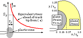
Setting the equivalent stress derived from the stress field ( 1) to equal the yield strength, the polar coordinates of the plastic zone boundary are found to be :-
( 2 ) r = ro ( (1-k)2 + 3 sin2θ/2 ) cos2θ/2 ; ro = 1/2π ( KI /Sy )2 = a/2 ( σ /Sy )2
where the constant k = 0 ( plane stress ) or k = 2ν ( plane strain ).
The proof of this is left as an exercise for the reader. The yield zones ( r,θ) plot out as shown at right above, from which characteristic zone sizes are :-
( i ) ry ≈ ro ( plane stress ) and ry ≈ ro /3 ( plane strain, ν = 0.3 )
Despite the questionable use of an elastic field to deduce the size and shape of a plastic zone, experiments confirm the above general findings. The derivation assumed perfectly plastic behaviour - to make some allowance for strain hardening, Sy is often taken as the average of the yield and ultimate strengths, whereupon it is referred to as the 'flow stress'.
For plastic effects to be negligible, other dimensions such as component width or ligament size, must be at least 50 times the plane strain plastic zone size, so :-
( 2a) bo ≈ 50 ro / 3 ≈ 2.5 ( KIc /Sy )2
In testing for plane strain fracture toughness therefore, the toughness must first be estimated to enable prediction of the minimum specimen dimensions, via ( 2a). The specimen is then made and tested. If the measured toughness is less than that assumed initially then the measured value is valid. Otherwise a larger specimen must be tested. It sometimes happens that the required specimen size or forces exceed the capacity of available testing machines, however it is usually possible, and perfectly valid, to test a specimen of the same thickness as the eventual component - ie. to measure the plane stress fracture toughness for use in the safety determination - but this toughness is not a material property.
 It is clear from ( 2) that the plastic zone size in front of a given crack must increase as the load increases, until eventually it extends right across the ligament as suggested here, so an upper limit of the load which can be withstood by a cracked component will correspond to gross plastic collapse across the ligament.