δc = a 8/π ( Sy /E' ) ln sec ( π/2 σF /Sy ) is the critical COD from ( ii) under failure load σF
= KIc2 / E' Sy on equating critical properties from ( iii).
But for an infinite plate KIc = σE √( π a ) and σP = Sy , so the interaction is
We have examined the effect of load and crack size when the material is either perfectly elastic or perfectly plastic - but how does a real ductile behave ? There are various approaches to answering this, ranging from simple interaction models between the two perfect mechanisms which we have already examined, through to the 'J-integral' technique involving an energy integral around the crack tip, and three- dimensional finite element models with elastic- plastic constitutive laws. Let's see how we might tackle the problem without the complexity ( or accuracy ) of these last methods.
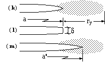
In practice, the inevitable yield zone ahead of the crack leads to a blunt crack tip. Thus, LEFM predicts a sharp tip to the crack of length a, as indicated in figure ( k) here. Further considerations require a yield zone, of size ry as shown in the previous section. In actuality ( l) the tip is stretched by an amount δ - the crack tip opening displacement or COD - which may be confirmed and measured experimentally.
Plastic effects are sometimes allowed for approximately by applying LEFM with an 'equivalent crack size', a' figure ( m), equal to the actual crack size plus some proportion of the plastic zone size. This 'small scale yielding correction' becomes increasingly inaccurate when the background stress reaches an appreciable fraction of yield.
δ, being strain-based, is a more suitable crack characterising parameter in the post -yield region, than is K which is stress -based. It may be shown that, for a centrally cracked infinite plate, the crack opening displacement and the plastic zone size are
| ( ii) | δ = a 8/π Sy /E' ln sec ( π/2 σ/Sy ) ; | where E' = E plane stress |
| ry = a ( sec ( π/2 σ/Sy ) - 1 ) | or E' = E/( 1 -ν2) plane strain |
| σ --> Sy | Tending towards plastic collapse; both δ and ry --> infinity | |
| σ = 2/3 Sy | The plastic zone and crack sizes are equal | |
| σ --> 0 | Tending towards LEFM ( negligible plasticity ) and enabling binomial expansion of ( ii) |
The advantages of COD as a crack characterising parameter should now be apparent - it is applicable over the whole range of loading, from linear elastic fracture to plastic collapse. One may expand on the COD theme as was done for stress intensity - configuration factors for non -infinite shapes, a critical maximum COD ( δc ) being a material property, and so on - however we shall restrict ourselves to the adaptation of the COD equation to provide an interaction formula for correlating the two extreme mechanisms noted above.
We take σE as the failure load when the mechanism is perfectly elastic ( LEFM ), and σP as the failure load when the mechanism is perfectly plastic ( plastic collapse ) - both of these can be computed by the methods of the previous sections. To find σF, the failure load when both elastic fracture and plastic collapse occur, we proceed as follows.
δc = a 8/π ( Sy /E' ) ln sec ( π/2 σF /Sy ) is the critical COD from ( ii) under failure load σF
= KIc2 / E' Sy on equating critical properties from ( iii).

But for an infinite plate KIc = σE √( π a ) and σP = Sy , so the interaction is
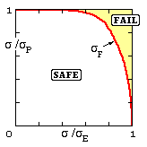
( 3 ) π/2 ( σF /σP ) = arccos ( exp [ - 1/2 { π/2 ( σE /σP ) }2 ] )
Predicting the failure load in this way via the COD equation, is known as the 'two criteria' or 'CEGB R6' approach to failure assessment - the failure locus from ( 3) plots as shown. Although ( 3) was deduced on the basis of a centrally cracked infinite plate, it is applicable to any configuration provided the axes are interpreted as load ratios rather than merely stress ratios.
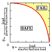 This approach is just one of many possible interaction models. Recalling the Column Analogy and adapting the nomenclature used with imperfect columns, it is apparent that the R6 locus is a particular case of the general interaction model shown here, which requires θ --> 1 as ψ --> 0 and θ --> 0 as ψ --> 1.
Various empirical correlations such as ( 1/θ - 1) ∗ ( 1/ψ - 1) = constant have been proposed - some of which describe particular experimental results better than others. One model which finds wide acceptance is the 'circular' failure locus θ2 + ψ2 = 1, that is
( 4) 1/σF2 = 1/σE2 + 1/σP2
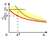
For an infinite plate KIc = σE √( π a ) and σP = Sy as above, so this may be written
( 4a) σF = Sy / √( 1 + a / a* )
in which a* = 1/π ( KIc / Sy )2 is a material property, like bo ( 2a)
The implication of critical crack size and limitations of crack size detection during inspection must be appreciated. If a crack of the critical size remains undetected by the inspection process then no amount of inspection will avert potential catastrophe.
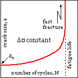
Steady loads only have been considered so far, for which we have noted the effect of increasing crack size on failure tendency. We now consider crack growth under alternating loads, ie. the fatigue process.
A typical crack history under a cyclic load of constant amplitude, Δσ, is sketched. A crack of size a1 exists initially, and grows in a stable, controlled manner until the critical crack size is approached - when crack growth rates increase out of hand and disaster strikes.
For a given material, the instantaneous rate of crack growth, the slope da/dN, is found to depend mainly upon the stress intensity range, ΔK, as expected - since
| - | it is the near tip field ( characterised by K ) which affects crack advance, and |
| - | fatigue is known to be greatly dependent upon the range of stress and of load ( the 'S' of the S-N diagram ) which is proportional to the range of stress intensity, as suggested here : |

| |
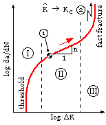
Closure of the crack, if and when the load becomes compressive, is usually allowed for by simply ignoring any sub -zero compressive excursions. Further evidence suggests that as the load changes from tensile to compressive, the crack closes while the load is still tensile - a result of residual stresses; however we shall neglect such complications here. So, accepting that intensity range is the main contributor to growth rate, the relationship is found to be as follows - this being a unique sigmoidal curve for each particular material. There are three stages
| I | Initiation. Relates to cleavage along grain boundaries at rates of the order of one lattice spacing per cycle ( 4 E-7 mm/cycle ); growth requires the stress intensity range to exceed some threshold value; influenced greatly by environment. This stage is byepassed if a crack exists prior to loading ( eg. the point 1 sketched may be the initial state ).
| 
|
| II | Stable Propagation. This is the most important stage, dealing with identifiable cracks (say > 0.1 mm ) growing in a stable manner. The direction of propagation is less random than in stage I and the material behaves more homogeneously. The material characteristic crack growth rate vs intensity range is approximately log-log linear throughout stage II and so we may write | |
| ( 5 ) | da/dN = C ΔKn
- the so-called Paris equation in which C and the index n are constant material properties. Selected values appear in the literature, it being customary to cite C indirectly by the stress intensity range, ΔKo , which corresponds to a certain crack growth rate, (da/dN)o - often 1 mm/Mc thus C = (da/dN)o / ΔKon | |
| III | Instability. Although important, this stage exists only for a very small fraction of the component's life, since the instability is catastrophic. The onset of stage III is dictated by the critical crack size being approached, that is by Kmax tending to Kc - 2 in the sketch.
One empirical modification of ( 5) which caters for both stages II and III, is : | |
| ( 5a) | da/dN = C ΔKn / { 1 - ( Kmax /K c )n }
Thus if Kmax << Kc, then the RHS denominator --> 1 corresponding to stage II; alternatively if Kmax --> Kc then da/dN tends to infinity ( stage III ). | |
( 5b ) { (da/dN)o ΔN12 /w } { Δσ √( πw) / ΔKo }n = ∫12( Y √α ) -n dα - ( Yc √αc ) -n ( α2 - α1 )
in which αc is the normalised critical crack size corresponding to Kc, and α2 ≤ αc.
The Pascal program Crack Growth enables integration along these lines; it assumes that the configuration factors, both elastic and plastic, are single functions of crack size.
When plane strain conditions are assured, then Kc ≡ KIc in the foregoing; otherwise it is suggested that the Kc predicted by the R6 ( or other elastic -plastic interaction relationship ) should be used.
It is usually the initial, rather than the final state of affairs which has largest bearing on component life, as is demonstrated here.